
Coring bit

a cutting bit and coring technology, applied in the field of cutting bits, can solve the problems of increasing the difficulty of removing cores, slowing down the drilling process, and requiring frequent attention, so as to increase the difficulty of removing cores, slow down the drilling process, and facilitate removal

Active Publication Date: 2007-03-13
FOREST CITY TOOL
View PDF12 Cites 94 Cited by
  • Summary
  • Abstract
  • Description
  • Claims
  • Application Information

AI Technical Summary

Benefits of technology

[0003]Many conventional coring bits have inner and outer parallel side wall faces which increases the difficulty in removing cores and slows the drilling process, particularly when used in repetitive commercial manufacturing operations.
[0004]Therefore in view of the problems and disadvantages of conventional large diameter drill or coring bits, the present invention was conceived and one of its objectives is ...

Problems solved by technology

When removing large diameter plugs or cores of material such cores often become lodged in the drill bit requiring frequent attention, down time and maintenance.
Many conventional coring bits have inner and outer parallel side wall faces which increases the difficulty in removing cores and slows the drilling process, particularly when used in repetitive commercial manufacturing operations.

Method used


Image

  • Coring bit
  • Coring bit
  • Coring bit

Examples


Embodiment Construction

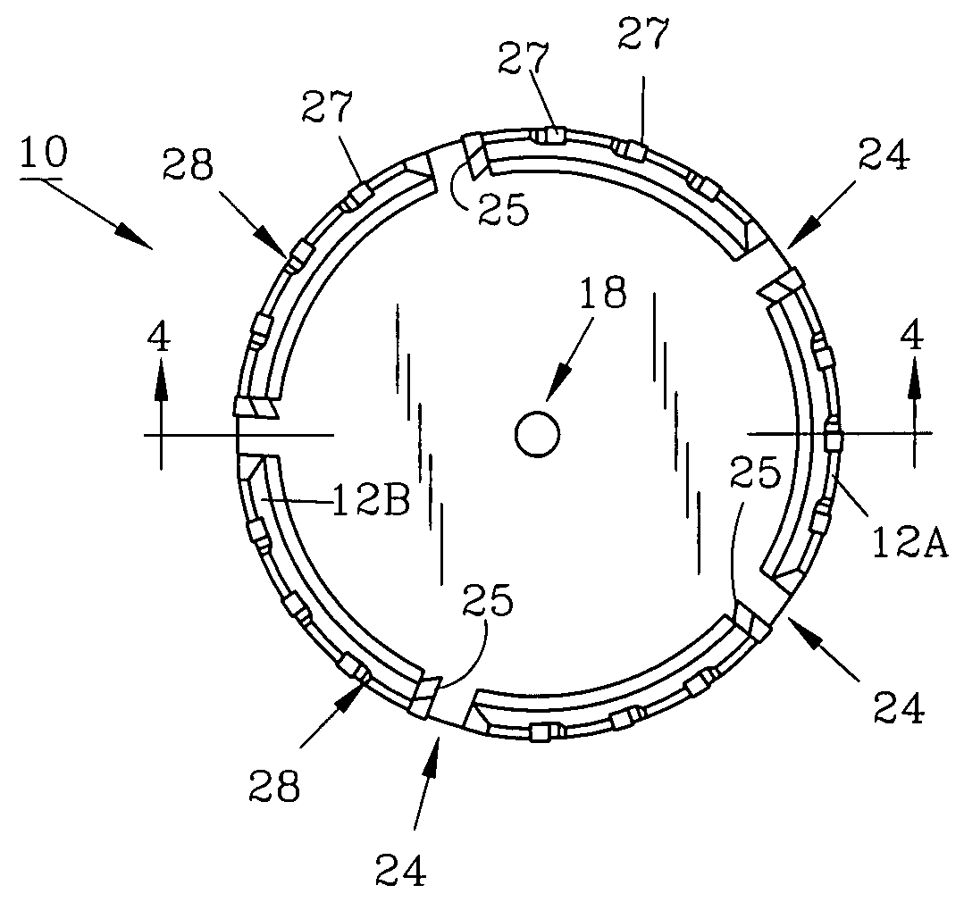
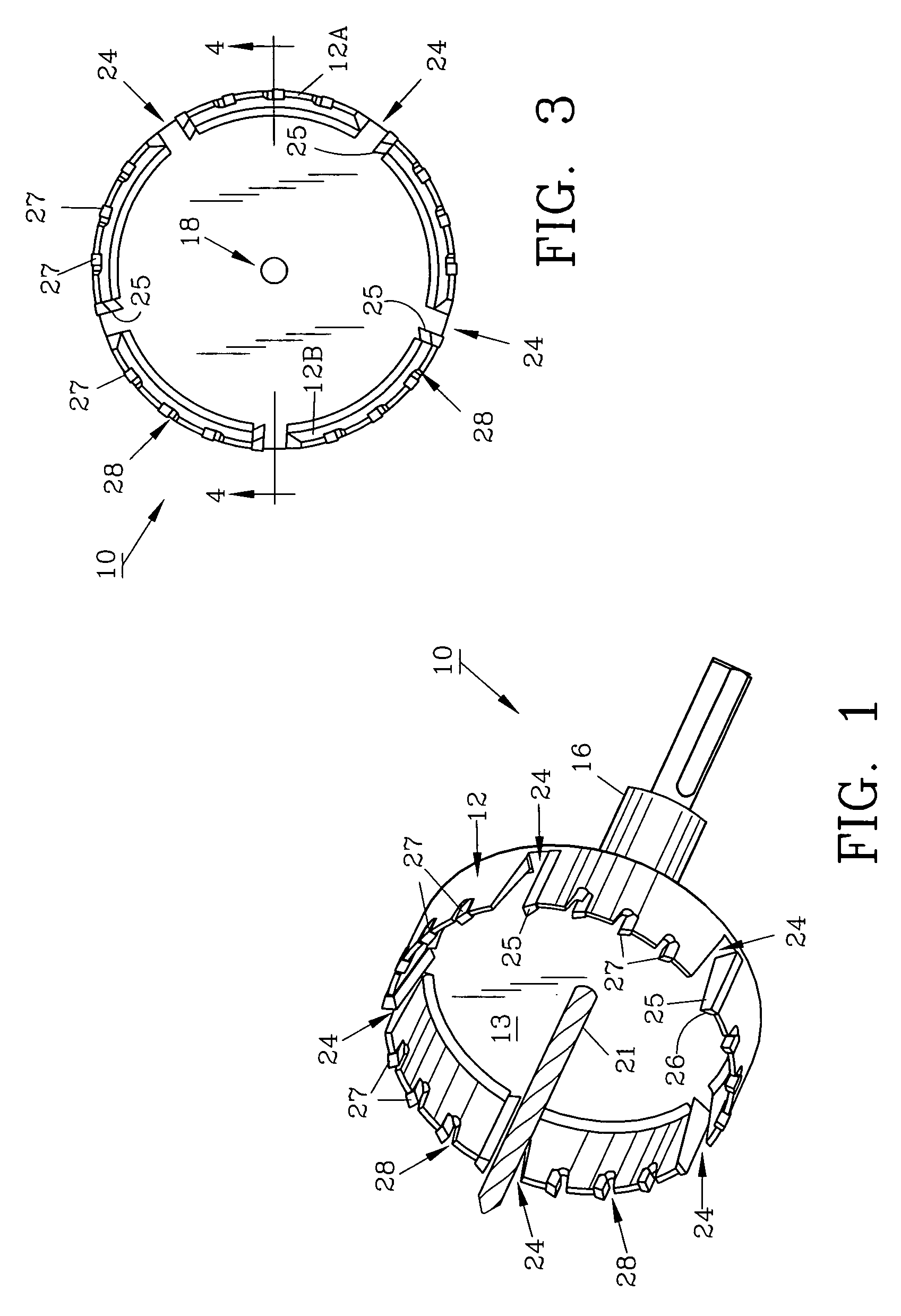
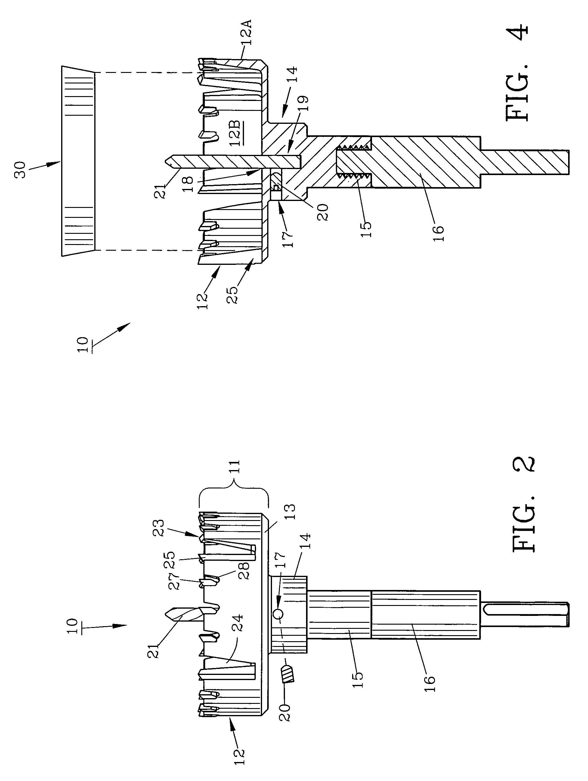
[0021]For a better understanding of the invention and its operation, turning now to the drawings, FIG. 1 illustrates a perspective view of preferred coring bit 10 for use with an electric power drill or the like. Coring bit 10 includes coring head 11 as illustrated in FIG. 2 including cylindrically shaped wall 12 and planar base 13. Shoulder 14 and neck 15 are also seen preferably integrally formed with base 13 in FIG. 2. Shoulder 14 includes threaded bore 17 for receiving allen screw 20 which acts as a bit lock. Base 13 includes central aperture 18 seen in FIG. 3 for receiving standard small diameter one-eighth inch (3.175 mm) center drill bit 21 which is coincidental with drill bit channel 19 extending within shoulder 14 as shown in FIG. 4. Another drill bit embodiment is seen in FIGS. 5, 6 and 7 in which center drill bit 31 with enlarged head 33 is preferably sharpened so that tip 32 is slightly off center. Head 23 is slightly larger in diameter than the diameter of shank 35. Off...


PUM

PropertyMeasurementUnit
Diameteraaaaaaaaaa
Shapeaaaaaaaaaa

Abstract

A coring bit provides easy core removal by utilizing a series of lateral blades which extend from the top cutting surface to the base of the bit. The lateral blades and inner faces of the coring bit are biased to provide a conical shape to the core thus permitting the core to be easily extracted. Vents positioned approximate the lateral blades allow chips, debris and waste to be quickly dispelled. Various types of small center drill bits aid in the initial coring stages.

Description

FIELD OF THE INVENTION[0001]The invention herein pertains to cutting bits as used with power tools such as electric drills and particularly pertains to cutting bits for forming large diameter apertures in various planar materials.DESCRIPTION OF THE PRIOR ART AND OBJECTIVES OF THE INVENTION[0002]Forming apertures in planar materials such as plywood sheets, wall board, various plastic materials and the like has been performed for many years using various types of drill bits with large diameter cutting surfaces. When removing large diameter plugs or cores of material such cores often become lodged in the drill bit requiring frequent attention, down time and maintenance. Of particular concern is the coring of thermoplastic materials which can melt and adhere to the inside of the bit, often fusing to the inner surfaces during the coring process.[0003]Many conventional coring bits have inner and outer parallel side wall faces which increases the difficulty in removing cores and slows the ...

Claims


Application Information

Patent Timeline
IPC IPC(8): B23B51/04
CPCB23B51/0413B23B51/0433Y10T408/8957Y10T408/895B23B2251/201B23B51/0426
Inventor WATSON, ANTHONY R.
Owner FOREST CITY TOOL
Learn More