Corner cube reflector, method of making the reflector and reflective display device including the reflector

a technology of reflector and cube, which is applied in the direction of optics, instruments, optical elements, etc., can solve the problems of unintentional color mixture, abnormal display state, and inevitably created gap between beads, and achieve excellent retroreflection properties and small pitch

Active Publication Date: 2007-03-13
SHARP KK
View PDF10 Cites 4 Cited by
  • Summary
  • Abstract
  • Description
  • Claims
  • Application Information

AI Technical Summary

Benefits of technology

[0023]In order to overcome the problems described above, an object of the present invention is to provide a corner cube reflector, which has a plurality of unit elements that are arranged at a very small pitch so as to exhibit excellent retroreflection property, and also provide a method of making such a corner cube reflector easily.
[0024]Another object of the present invention is to provide a reflective display device including such a corner cube reflector, which realizes excellent display performance.
[0045]According to various preferred embodiments of the present invention described above, the retroreflection property of a corner cube reflector, having a plurality of unit elements that are arranged at a very small pitch, can be improved. Among other things, the present invention is particularly advantageous in that the retroreflection property of a corner cube reflector is improvable even without increasing the shape precision thereof.
[0046]In addition, according to various preferred embodiments of the present invention described above, such a corner cube reflector can be obtained easily.
[0047]Furthermore, if a retroreflector is formed using such a corner cube reflector, then a reflective display device including such a retroreflector can exhibit improved display performance.

Problems solved by technology

In that case, the display might exhibit an abnormal state.
For example, an incoming light ray that has passed a red color filter before reaching the retroreflector 8 may pass through a green or blue color filter on its way back, thus possibly causing a color mixture unintentionally.
In a reflector densely packed with beads on the other hand, a gap is created inevitably between the beads, no matter how densely those beads are packed, and such a gap never contributes to retroreflection.
As can be seen, in those reflectors obtained by densely packing beads or arranging triangular pyramidal concave portions, the percentage of the non-retroreflective portions to the overall reflector is too high to achieve sufficiently high retroreflectivity.
Actually, however, it is extremely difficult even to make a square corner cube reflector at such a small arrangement pitch (of 250 μm or less, for example).
Likewise, none of the other conventional methods of making square corner cubes mechanically such as a plate method and a pin bundling method is suitable to making a square corner cube reflector at that small arrangement pitch.
Nevertheless, it is still difficult at this time to make a square corner cube reflector at a small enough arrangement pitch and with a sufficiently high retroreflection property by any of the methods mentioned above.
According to the non-mechanical methods mentioned above, it is difficult to make a square corner cube array in an almost ideal shape, and therefore, the actual retroreflection property deteriorates significantly from its theoretical one.
More specifically, as for a square corner cube obtained by a photochemical method as disclosed in Japanese Laid-Open Publication No. 7-205322, it is difficult to ensure high plane precision (i.e., planarity).
Actually, though, such a strict process control is hard to realize.
Thus, it is not easy to make a square corner cube array in its intended shape by such a method, either.
In particular, the smaller the arrangement pitch of the unit elements, the lower the shape precision of the square corner cube array and the more difficult it is to improve the retroreflection property sufficiently.

Method used


Image

  • Corner cube reflector, method of making the reflector and reflective display device including the reflector
  • Corner cube reflector, method of making the reflector and reflective display device including the reflector
  • Corner cube reflector, method of making the reflector and reflective display device including the reflector

Examples


embodiment 1

[0100]Hereinafter, a corner cube reflector according to a first specific preferred embodiment of the present invention will be described.

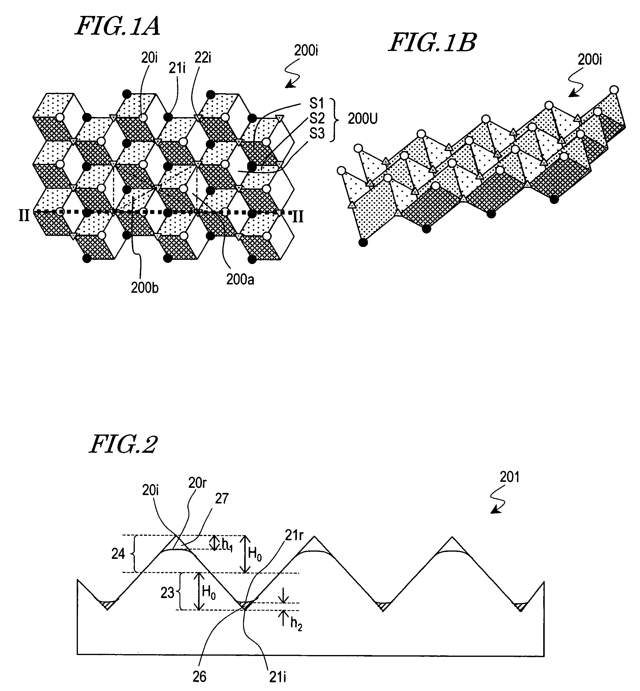
[0101]As shown in FIGS. 5B or 5C, the corner cube reflector 202 of this preferred embodiment includes a bottom portion with almost no unwanted planes and a peak portion, which has a rounded shape due to a deformed portion as shown in FIG. 5B or a partially missing portion as shown in FIG. 5C. Accordingly, the level of the peak point 20r is lower than that of the ideal peak point 20i. The unit elements may have an arrangement pitch of 10 μm, for example.

[0102]The corner cube reflector 202 of this preferred embodiment may be fabricated by the following method, for example.

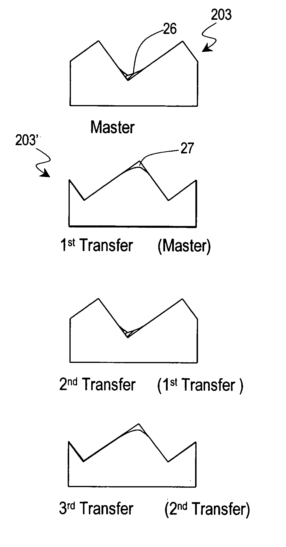
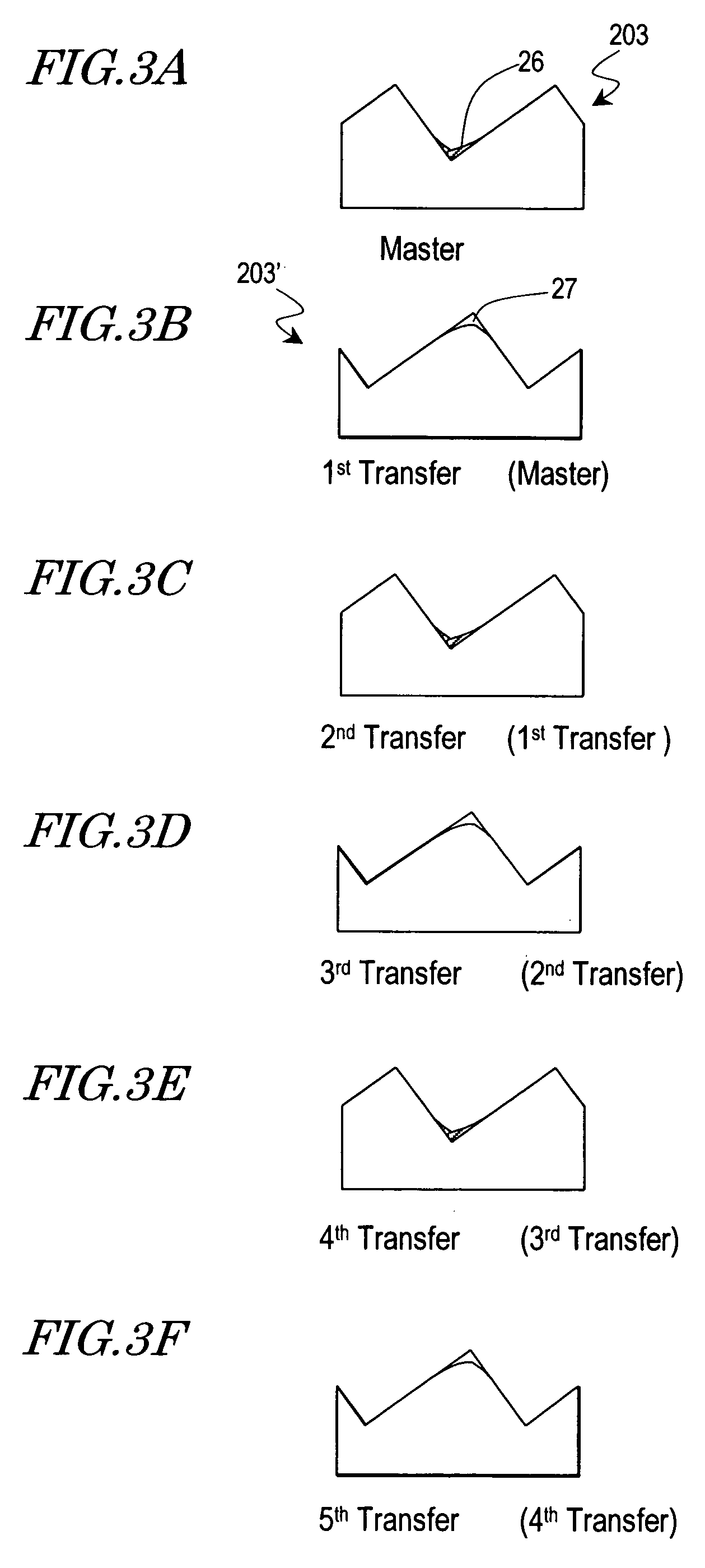
[0103]Hereinafter, a method of making the corner cube array master 203 will be described with reference to FIGS. 6A through 6I and FIGS. 7A through 7I. FIGS. 6A through 6I are plan views of the substrate in respective process steps. FIGS. 7A through 7I are cross-sectional views sche...

embodiment 2

[0154]Hereinafter, a reflective display device according to a preferred embodiment of the present invention will be described.

[0155]First, the configuration of a reflective display device 400 according to this preferred embodiment will be described with reference to FIG. 15. The reflective display device 400 includes a corner cube reflector (i.e., a retroreflector in this case) 48 and a liquid crystal cell 40, which is provided closer to the viewer than the corner cube reflector 48 is. The corner cube reflector 48 includes a corner cube array 49 and a metal layer 50 deposited on the surface of the corner cube array 49. The corner cube array 49 is formed by the same method, and has the same configuration, as the corner cube array 202 of the first preferred embodiment described above. Accordingly, to the viewer's eyes, the corner cube array 49 consists of a plurality of concave portions with a relatively good shape and a plurality of convex portions with a more incomplete shape than t...


PUM

PropertyMeasurementUnit
distanceaaaaaaaaaa
distanceaaaaaaaaaa
focusing angleaaaaaaaaaa

Abstract

A corner cube reflector includes a two-dimensional arrangement of unit elements. The unit elements are arranged at a pitch of 200 μm or less. As viewed in a direction from which incoming light is coming, each unit element has a peak point and a bottom point. A peak portion, including the peak point, has an excessive portion and / or a missing portion as compared with an ideal peak portion of an ideal corner cube. The level of the peak point is lower than that of the ideal peak point of the ideal corner cube. An average level difference h2 between the level of the bottom point and that of an ideal bottom point of the ideal corner cube is smaller than an average level difference h1 between the level of the peak point and that of the ideal peak point.

Description

BACKGROUND OF THE INVENTION[0001]1. Field of the Invention[0002]The present invention relates to a corner cube reflector, a method of making the corner cube reflector, and a reflective display device including the corner cube reflector.[0003]2. Description of the Related Art[0004]Various configurations have been proposed for a reflective liquid crystal display device with a retroreflector (see Japanese Laid-Open Publication No. 2002-107519, Japanese Patent No. 3216584, and Japanese Laid-Open Publication No. 2002-287134, for example). Each of those reflective liquid crystal display devices uses no polarizers and therefore can conduct a display operation with increased brightness, and is also expected to achieve a display at a higher contrast ratio. As used herein, the “retroreflector” refers to an optical element that has a two-dimensional arrangement of very small unit elements so as to reflect any incoming light ray back to the source by way of multiple reflective surfaces thereof,...

Claims


Application Information

Patent Timeline
Patent Type & Authority Patents(United States)
IPC IPC(8): G02B5/124G02F1/1335
CPCG02B5/124Y10S359/90G02F1/133553G02F1/1335
Inventor SAWAYAMA, YUTAKAFUJIWARA, SAYURIKANBE, MAKOTOMINOURA, KIYOSHIIHARA, ICHIRO
Owner SHARP KK
Why Eureka
Try Eureka