
Flow regulator for aerosol drug delivery and methods

a flow regulator and aerosol technology, applied in the direction of valves, respirators, operating means/releasing devices, etc., can solve the problems of low patient acceptance, degraded drugs, oral delivery, etc., and achieve the effect of adequate flow ra

Inactive Publication Date: 2007-03-06
NOVARTIS FARMA
View PDF143 Cites 41 Cited by
  • Summary
  • Abstract
  • Description
  • Claims
  • Application Information

AI Technical Summary

Benefits of technology

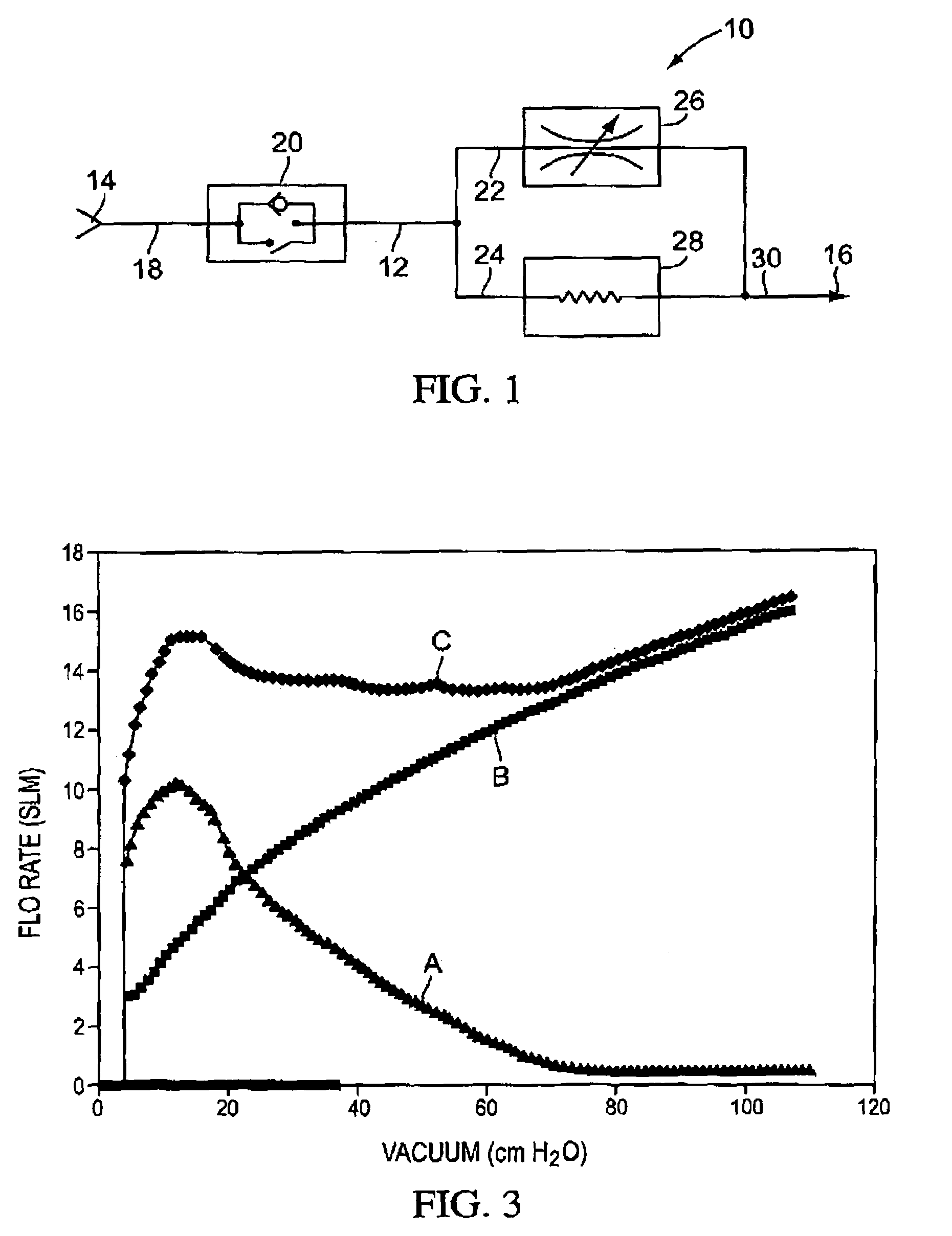
[0008]In one aspect, the flow path arrangement has a series-parallel configuration with a first flow path that divides into a second flow path and a third flow path. Further, the threshold valve is in the first flow path, the flow regulating valve is in the second flow path, and the powder is coupled to the third flow path. With such a configuration, the flow regulating valve closes at a greater rate to provide an increased flow resistance as the vacuum increases, i.e., the flow regulating valve has a highly non-linear orifice area / vacuum relationship, to maintain the total flow rage within the desired range.
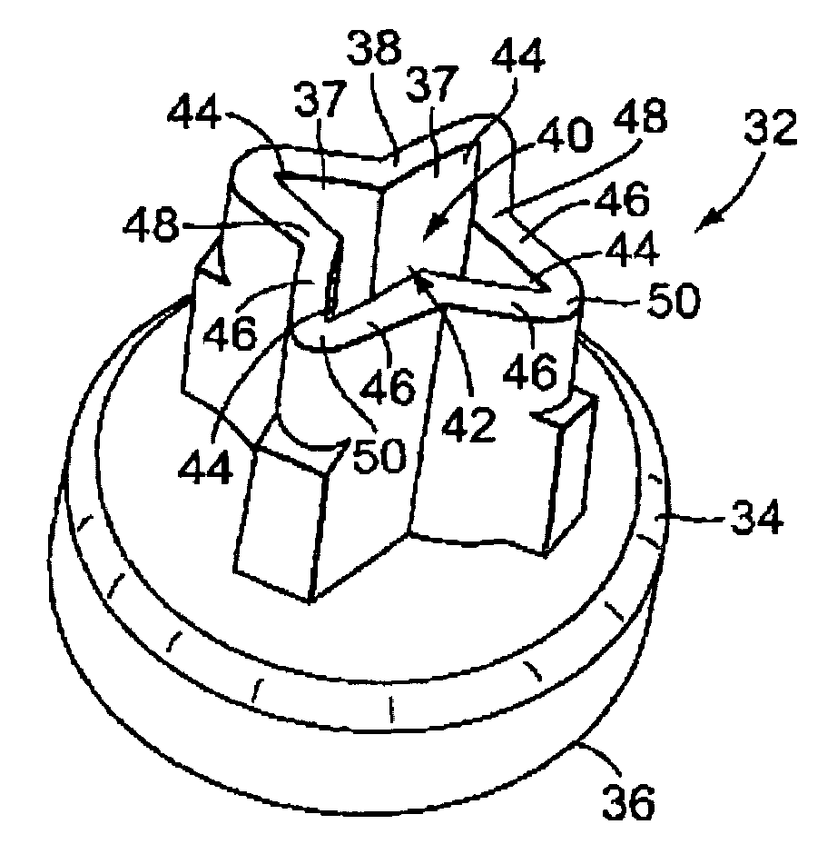
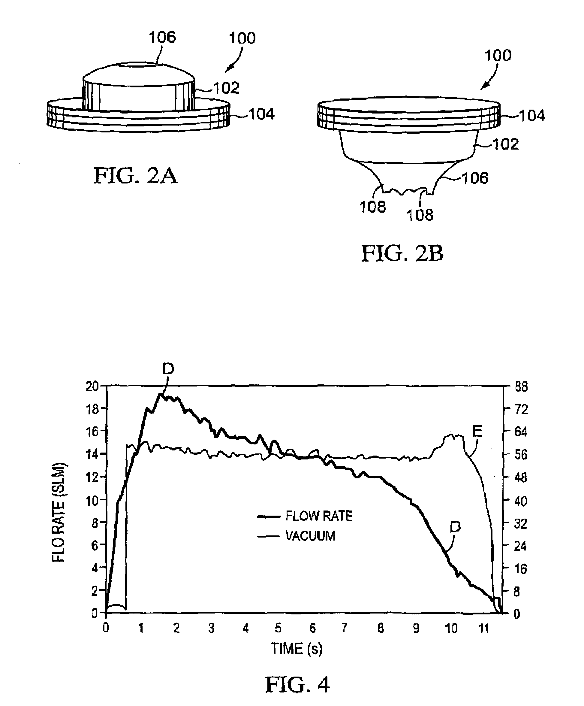
[0010]In one particular configuration, the flow regulating valve comprises at least one deformable wall and an opposing surface. The deformable wall moves toward the opposing surface as the vacuum downstream of the flow regulating valve increases, thereby increasing flow resistance to regulate the flow rate. For example, in one embodiment, the flow regulating valve comprises a valve body having an inlet end, an outlet end and a gas flow passage between the inlet end and the outlet end. The valve body is constructed of a resilient material and the valve body at the outlet end has a central region and a plurality of extending regions that extend outwardly from the central region. The extending regions are drawn together to limit the flow of gases through the gas flow passage as the vacuum at the outlet end increases. Further, such an embodiment has a highly non-linear orifice area / vacuum relationship so that the valve closes rapidly as higher vacuums are produced. Further, the valve body may include a boundary layer step just beyond the inlet to insure boundary layer separation. In this way, the valve operates in a predictable manner across a wide range of vacuums and flow rates.

Problems solved by technology

However, oral delivery can in some cases be undesirable in that many drugs are degraded in the digestive tract before they can be absorbed.
One disadvantage to this approach is low patient acceptance.
Utilization of the patient's inspired gases can be challenging in several respects.
Another challenge in utilizing the patient's inspired gases is that the inspiration flow rate can drastically vary between individuals.

Method used


Image

  • Flow regulator for aerosol drug delivery and methods
  • Flow regulator for aerosol drug delivery and methods
  • Flow regulator for aerosol drug delivery and methods

Examples


Embodiment Construction

[0031]The invention provides systems and methods for the administration of aerosolized pharmaceutical formulations using the flow of respiratory gases produced by a patient. The pharmaceutical formulations that may be aerosolized include powdered medicaments, liquid solutions or suspensions, and the like, and may include an active agent. The devices of the present invention may be used for single or multiple administrations.

[0032]In some embodiments, the flow of respiratory gases produced by the patient is employed to extract the pharmaceutical formulation from a receptacle, to deagglomerate the pharmaceutical formulation and deliver the pharmaceutical formulation to the patient's lungs. One particular advantage of the invention is the ability to perform such functions independent of the patient's natural inhalation flow rate. Hence, in one aspect of the invention, the inhaled respiratory gases are controlled so that they remain within an acceptable range of flow rates to adequately...


PUM


Abstract

An aerosolization device comprises a housing having a mouthpiece, and a flow path arrangement in fluid communication with the mouthpiece. The flow path arrangement has a flow regulating valve and a threshold valve, where the threshold valve is configured to open at a first vacuum level and to close at a second vacuum level that is less than the first vacuum level. The housing includes a region that is adapted to hold a powder in fluid communication with the flow path arrangement so that air drawn through the mouthpiece opens the threshold valve once the first vacuum level is exceeded and remains open until the vacuum falls below the second vacuum level. The flow rate of the air drawn through the mouthpiece is regulated by the flow regulating valve to remain within a certain range while the threshold valve remains open.

Description

BACKGROUND OF THE INVENTION[0001]This invention relates generally to the field of drug delivery, and in particular to the delivery of pharmaceutical formulations to the lungs. More specifically, the invention relates to the aerosolization of pharmaceutical formulations using air flows created by patient inhalation, and to the regulation of such air flows such that the pharmaceutical formulation is provided to the patient within a desired flow rate range.[0002]Effective drug delivery to a patient is a critical aspect of any successful drug therapy, and a variety of drug delivery techniques have been proposed. For example, one convenient method is the oral delivery of pills, capsules, elixirs and the like. However, oral delivery can in some cases be undesirable in that many drugs are degraded in the digestive tract before they can be absorbed. Another technique is subcutaneous injection. One disadvantage to this approach is low patient acceptance. Other alternative routes of administr...

Claims


Application Information

Patent Timeline
IPC IPC(8): A62B9/02A61M16/00A61M15/00
CPCA61M15/0086A61M15/002A61M15/0016A61M15/0091A61M2202/064A61M15/0093
Inventor ALSTON, WILLIAMSMEULDERS, STEPHEN
Owner NOVARTIS FARMA
Learn More