
Systems and methods for increasing cerebral spinal fluid flow

a cerebral spinal fluid and system technology, applied in the field of intracranial and intraocular pressure, can solve the problems of brain swelling, death or serious brain injury,

Inactive Publication Date: 2007-03-06
ZOLL MEDICAL CORPORATION
View PDF148 Cites 63 Cited by
  • Summary
  • Abstract
  • Description
  • Claims
  • Application Information

AI Technical Summary

Benefits of technology

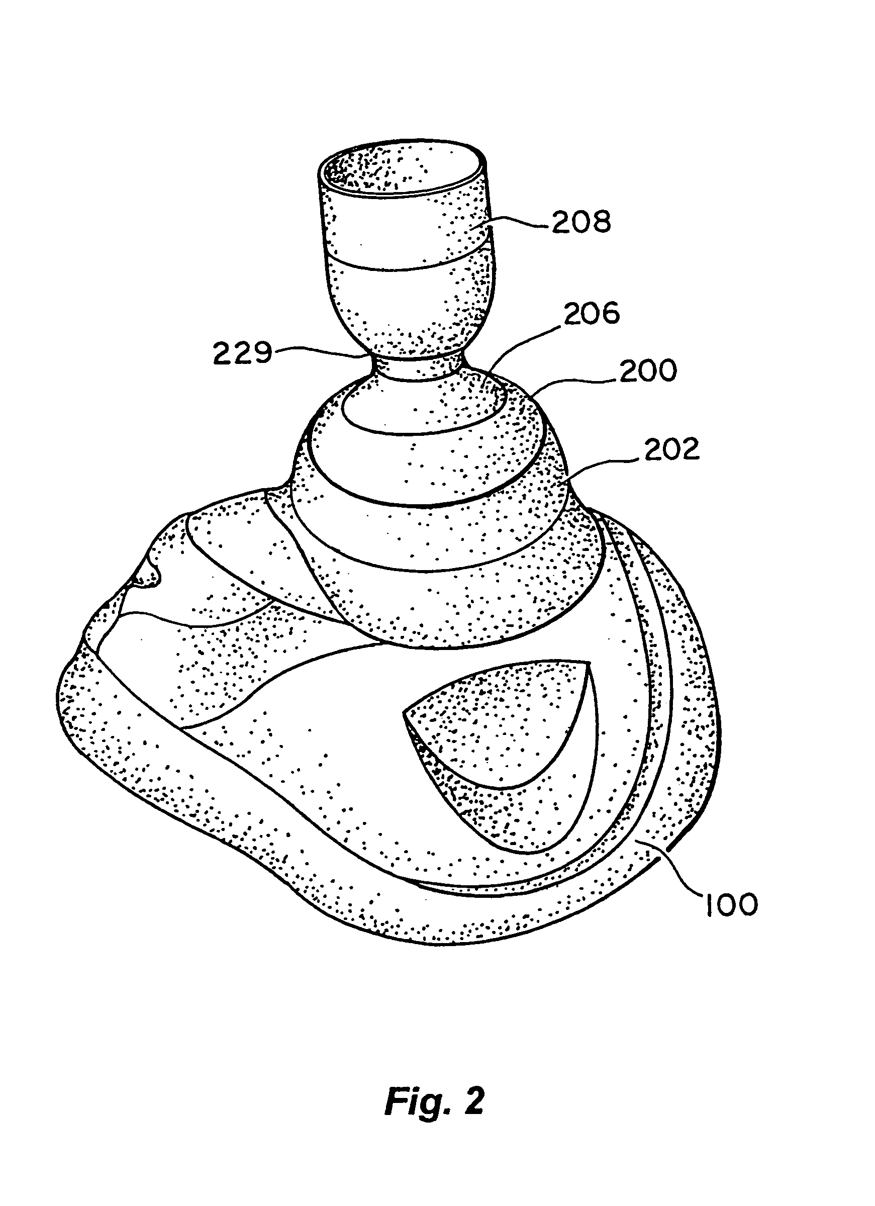
[0004]In one embodiment, the invention provides a device for decreasing intracranial or intraocular pressures. The device comprises a housing having an inlet opening and an outlet opening that is adapted to be interfaced with a person's airway. The device further includes a valve system that is operable to regulate respiratory gas flows through the housing and into the person's lungs during spontaneous or artificial inspiration. The valve system assists in lowering intrathoracic pressures during inspiration to continuously or intermittently lower pressures in the venous blood vessels that transport blood out of the head to thereby reduce intracranial or intraocular pressures.
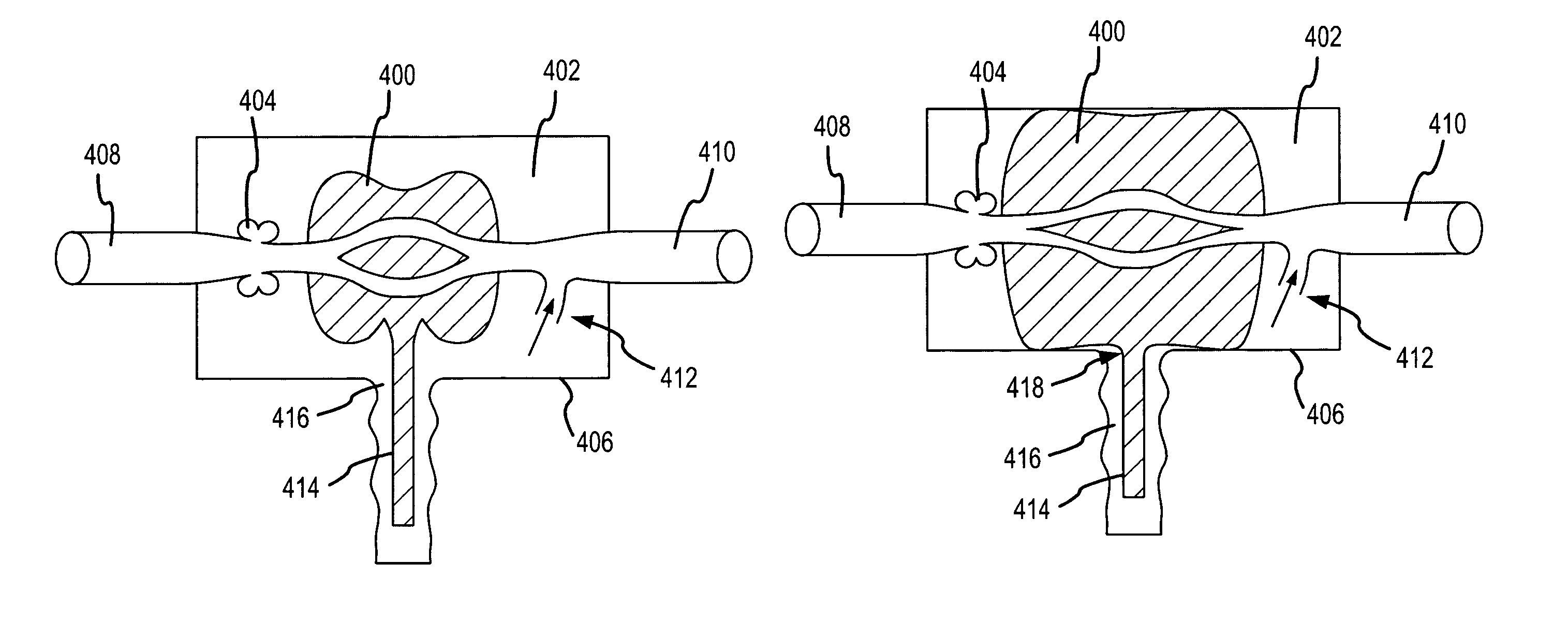
[0005]Such a device may also be used to facilitate movement of cerebral spinal fluid. In so doing, intracranial pressures may be further reduced. Such a device may therefore be used to treat those suffering from head trauma associated with elevated intracranial pressures as well as those suffering from heart conditions that increase intracranial pressures.
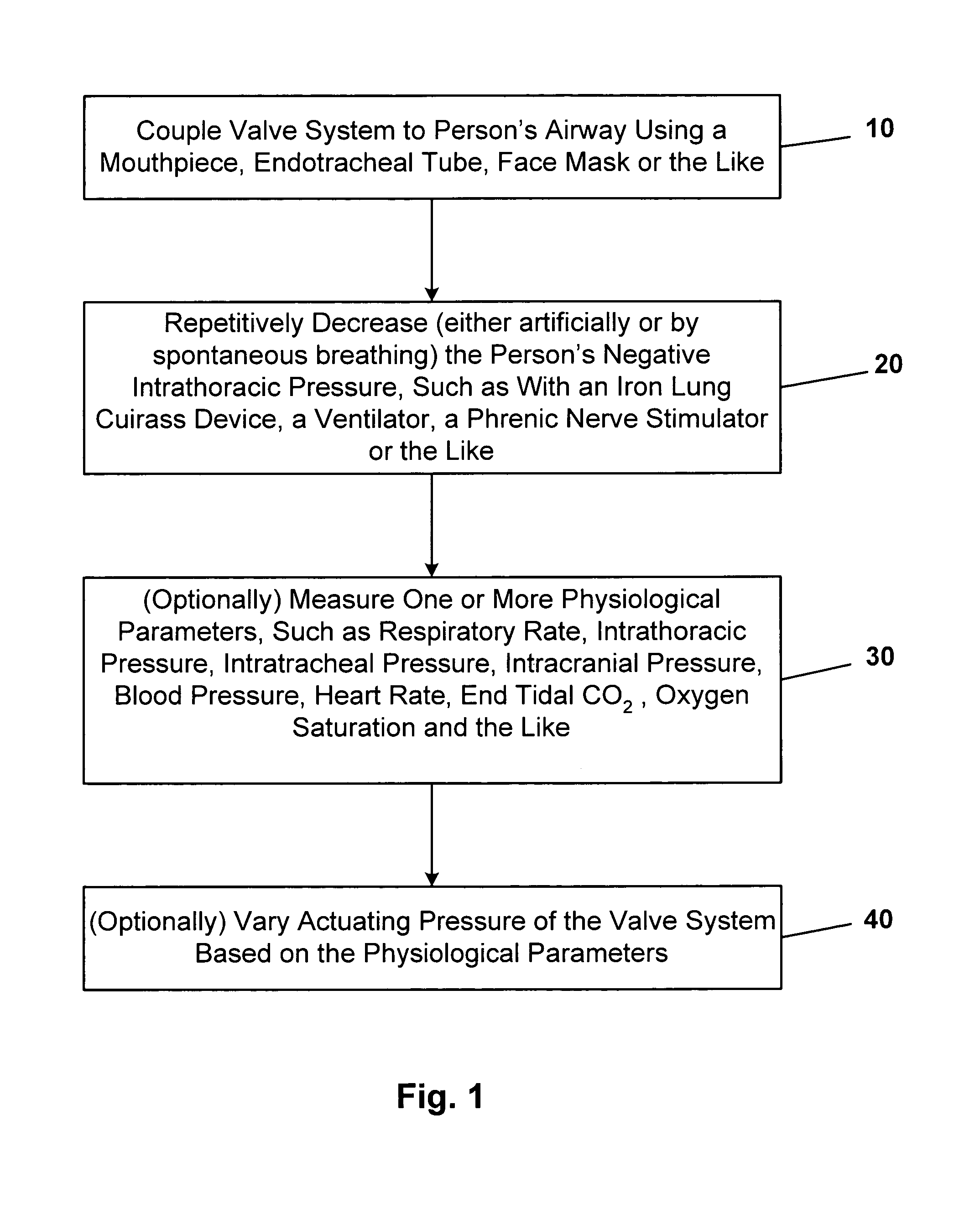
[0012]In another embodiment, the invention provides a method for decreasing intracranial or intraocular pressures. According to the method, a valve system is coupled to a person's airway and is configured to at least periodically reduce or prevent respiratory gases from flowing to the person's lungs. With the valve system coupled to the airway, the person's negative intrathoracic pressure is repetitively decreased to in turn repetitively lower pressures in the venous blood vessels that transport blood out of the head. In so doing, intracranial and intraocular pressures are reduced. Such a method also facilitates movement of cerebral spinal fluid. In so doing, intracranial pressures are further reduced. As such, this method may also be used to treat a person suffering from head trauma that is associated with elevated intracranial pressures as well as those suffering from heart conditions that increase intracranial pressures, such as atrial fibrillation and heart failure.
[0015]To couple the valve system to the airway, a variety of techniques may be used, such as by using a mouthpiece, an endotracheal tube, a face mask or the like. Further, the respiratory gases may be prevented from entering the lungs through the valve system until a negative intrathoracic pressure in the range from about 0 cmH2O to about −25 cmH2O is achieved, at which time the valve system permits respiratory gases to flow to the lungs.

Problems solved by technology

Head trauma often results in swelling of the brain.
Because the skull cannot expand, the increased pressures within the brain can lead to death or serious brain injury.
While a number of therapies have been evaluated in order to reduce brain selling, including use of hyperventilation and steroids, an effective way to treat intracranial pressures remains an important medical challenge.

Method used


Image

  • Systems and methods for increasing cerebral spinal fluid flow
  • Systems and methods for increasing cerebral spinal fluid flow
  • Systems and methods for increasing cerebral spinal fluid flow

Examples


example 1

[0051]The following is a non-limiting example illustrating how intracranial pressures may be lowered according to the invention. In this example, 30 kg pigs were anesthetized with propofol. Using a micromannometer-tipped electronic Millar catheter inserted below the dura, intracranial pressures were measured continuously in the spontaneously breathing pigs. Intrathoracic pressures (ITP) were recorded using a Millar catheter placed in the trachea at the level of the carina. After stabilizing the pigs blood pressure, heart rate, and ventilation rate, intracranial pressures (ICP) and intrathoracic pressures were recorded, with 0 cmH2O inspiratory impedance and then with inspiratory impedances of 5, 10, 15, and 20 cm H2O. Inspiratory impedance was achieved using an impedance threshold valve (ITV) as described in FIGS. 2–5.

[0052]At base, the intracranial pressure was approximately 8 / 4 mmHg. With increasing amounts of inspiratory impedance, the intracranial pressure was lowered proportion...

example 2

[0053]In this example, intracranial pressures were increased in the setting of recovery from cardiac arrest. The example used a pig model with ventricular fibrillation for 6 minutes followed by cardiopulmonary resuscitation for 6 minutes, followed by defibrillation. Spontaneous breathing resulted in an up to 50% decrease in intracranial pressures when the animals breathed through an inspiratory impedance of 10 cm H2O using a valve system similar to Example 1.

[0054]In all examples above, the intrathoracic pressure decreased relative to the rest of the body, creating a suction effect that reduced the pressure in the venous blood vessels draining the brain, thereby reducing intracranial pressures.

[0055]The invention further provides techniques and devices for reducing intracranial pressure (ICP) by facilitating movement of cerebral spinal fluid (CFS). There are a number of causes of increased ICP including: head injury, ischemia, osmolar imbalance, cerebral edema, tumors, complications...


PUM


Abstract

In one embodiment, the invention provides a device for decreasing intracranial or intraocular pressures. The device comprises a housing having an inlet opening and an outlet opening that is adapted to be interfaced with a person's airway. The device further includes a valve system that is operable to regulate respiratory gas flows through the housing and into the person's lungs during spontaneous or artificial inspiration. The valve system assists in lowering intrathoracic pressures during each inspiration to repetitively lower pressures in the venous blood vessels that transport blood out of the head to thereby reduce intracranial or intraocular pressures.

Description

CROSS REFERENCE TO RELATED APPLICATIONS[0001]This application is a continuation-in-part of U.S. patent application Ser. No. 10 / 426,161, filed Apr. 28, 2003, the complete disclosure of which is herein incorporated by reference.BACKGROUND OF THE INVENTION[0002]This invention relates generally to the field of intracranial and intraocular pressures. More specifically, the invention relates to devices and methods for decreasing intracranial and intraocular pressures, such as those resulting from a traumatic head injury.[0003]Head trauma is generally regarded as the leading cause of morbidity and mortality in the United States for children and young adults. Head trauma often results in swelling of the brain. Because the skull cannot expand, the increased pressures within the brain can lead to death or serious brain injury. While a number of therapies have been evaluated in order to reduce brain selling, including use of hyperventilation and steroids, an effective way to treat intracranial...

Claims


Application Information

Patent Timeline
IPC IPC(8): A61M16/00A62B18/10A62B7/10A62B9/02A61M16/06A61M16/08A61M16/20
CPCA61M16/20A61M16/0825A61M16/06A61M2230/06A61M2230/205A61M2230/50A61M2230/432A61M16/107A61M16/208
Inventor LURIE, KEITH G.
Owner ZOLL MEDICAL CORPORATION
Learn More