Fiber-based optical low coherence tomography

a low-coherence tomography and fiber-based technology, applied in the field of optics, can solve the problems of limiting the detection of fast transient birefringence changes in samples, the implementation of non-pm fiber-based setups of polarization-sensitive olcr systems with standard single-mode fibers is complicated, and the sample is difficult to reliably measure birefringence, etc., to achieve the effect of adding a sample contras

Inactive Publication Date: 2007-02-13
BOARD OF RGT THE UNIV OF TEXAS SYST
View PDF28 Cites 81 Cited by
  • Summary
  • Abstract
  • Description
  • Claims
  • Application Information

AI Technical Summary

Benefits of technology

[0012]One of many advantages of the present invention is that it provides a mechanism by which to obtain additional contrast of a sample. For example, the present invention may be used to image and / or identify structural components of a sample or material, especially in materials (e.g., biologic materials) whereby functional information is associated with transient changes in birefringence. In addition, the present invention may be used to monitor, in real-time, surgical procedures, especially those that rely on photothermal injury mechanisms or changes in subsurface tissue components. The present invention may also be used as a feedback signal to control laser procedures in real time (e.g., dosimetry) and in catheters using optical fiber to deliver light.

Problems solved by technology

Unfortunately, fiber implementation of a polarization-sensitive OLCR system with standard single mode fiber is complicated since polarization state in a single mode fiber randomly fluctuates due to microscopic defects in the fiber, core ellipticity and external environmental perturbations.
Non-PM fiber-based setups cannot reliably measure birefringence of a sample with a single measurement even when using short lengths of fiber in the interferometer.
Multiple measurements for birefringence characterization, however, limit detection of fast transient birefringence changes in a sample and are subject to any motion related artifact between multiple acquisitions.
Although PM fiber based polarization-sensitive OCLR have been proposed to solve such problems, functioning and working systems have not been adequately constructed.
Another disadvantage of current PM-OLCR systems is that they use bulk interferometric setups to interrogate samples for birefringence measurement.

Method used


Image

  • Fiber-based optical low coherence tomography
  • Fiber-based optical low coherence tomography
  • Fiber-based optical low coherence tomography

Examples


Embodiment Construction

[0023]Although making and using various embodiments of the present invention are discussed in detail below, it should be appreciated that the present invention provides many inventive concepts that may be embodied in a wide variety of contexts. The specific aspects and embodiments discussed herein are merely illustrative of ways to make and use the invention, and do not limit the scope of the invention.

[0024]In the description which follows like parts may be marked throughout the specification and drawing with the same reference numerals, respectively. The drawing figures are not necessarily to scale and certain features may be shown exaggerated in scale or in somewhat generalized or schematic form in the interest of clarity and conciseness.

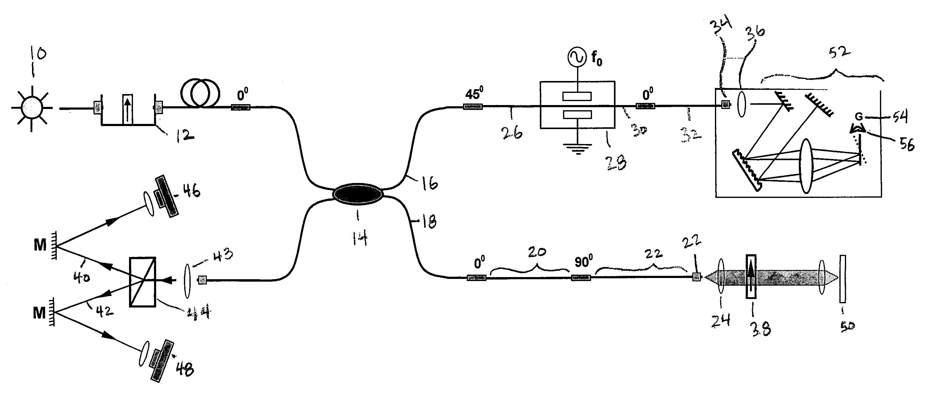
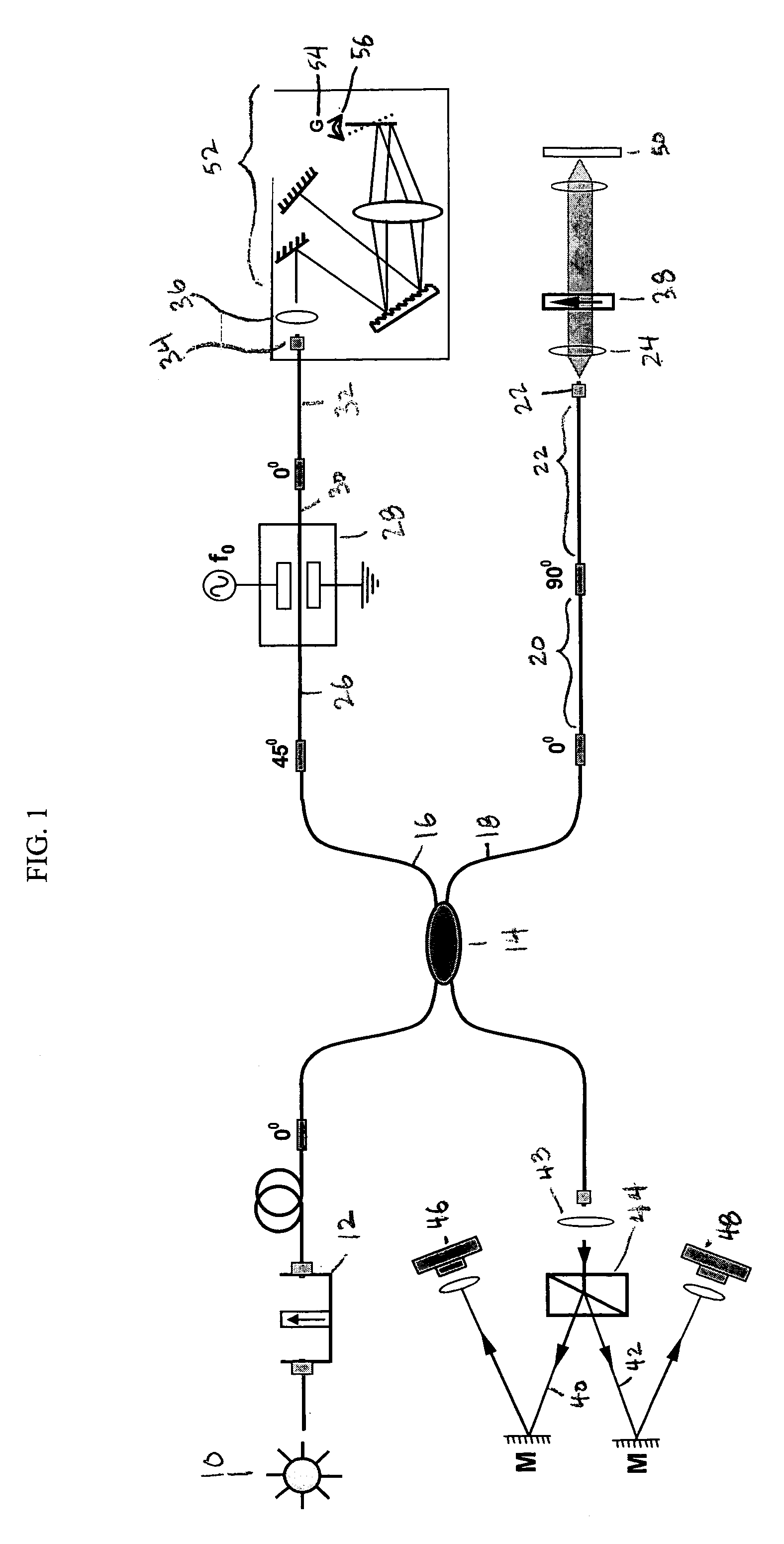
[0025]FIG. 1 depicts one aspect of the present invention, the PM fiber polarization-sensitive OLCR system, also referred to as the PM fiber-based polarization sensitive optical coherence tomography (PS-OCT). A light source 10 emits broadband ligh...


PUM

PropertyMeasurementUnit
coherence lengthaaaaaaaaaa
focal lengthaaaaaaaaaa

Abstract

Generally, and in one form of the present invention, is a polarization-maintaining fiber-based polarization sensitive optical low coherence reflectometer for depth resolved birefringence measurement. With the present invention, linear birefringence of a sample may be measured from data recorded in a single A-Scan. In addition, the present invention provides for the simultaneous measurement of retardation and orientation of birefringent axes, wherein measured retardation is insensitive to sample rotation in the plane perpendicular to ranging.

Description

CROSS-REFERENCES TO RELATED APPLICATIONS[0001]This application claims the benefit of U.S. Provisional Patent Application No. 60 / 261,658, filed Jan. 12, 2001. This application is a continuation-in-part of U.S. patent application Ser. No. 10 / 044,421, filed Jan. 11, 2002, now issued as U.S. Pat. No. 6,665,456 and incorporated herein by reference.BACKGROUND OF THE INVENTION[0002]The present invention relates generally to the field of optics and in particular to an interferometric system for birefringence characterization of one or more samples.[0003]Precise characterization of static or dynamic material birefringence is important and useful in applications that range from testing of optical components to measuring the viability and function of biologic tissue. While there are techniques that measure linear birefringence of samples, there remains a need for improved resolution and characterization, especially for samples or materials that are highly transparent, turbid and / or highly scat...

Claims


Application Information

Patent Timeline
Patent Type & Authority Patents(United States)
IPC IPC(8): G02B6/27G01B9/02G01J4/00G02B6/26A61B5/026G01N21/47G01P5/00G01P5/26G02B6/34
CPCG01N21/4795G01P5/001G01P5/26G01B9/02045G01B9/02027G01B9/02091G01B9/0201A61B5/0066A61B5/0261G01B2290/45G01B2290/70
Inventor DAVE, DIGANT P.MILNER, THOMAS E.AKKIN, TANER
Owner BOARD OF RGT THE UNIV OF TEXAS SYST
Why Eureka
Try Eureka