
Electrosurgical mode conversion system

a conversion system and electrosurgical technology, applied in the field of electrosurgical mode conversion system, can solve the problems of unintended tissue damage, burns or other complications, inadvertent activation of rf energy source, and tissue damage that could occur from such an event, so as to reduce the number of cables and avoid unintentional effects

Inactive Publication Date: 2007-02-13
MICROLINE SURGICAL INC
View PDF21 Cites 145 Cited by
  • Summary
  • Abstract
  • Description
  • Claims
  • Application Information

AI Technical Summary

Benefits of technology

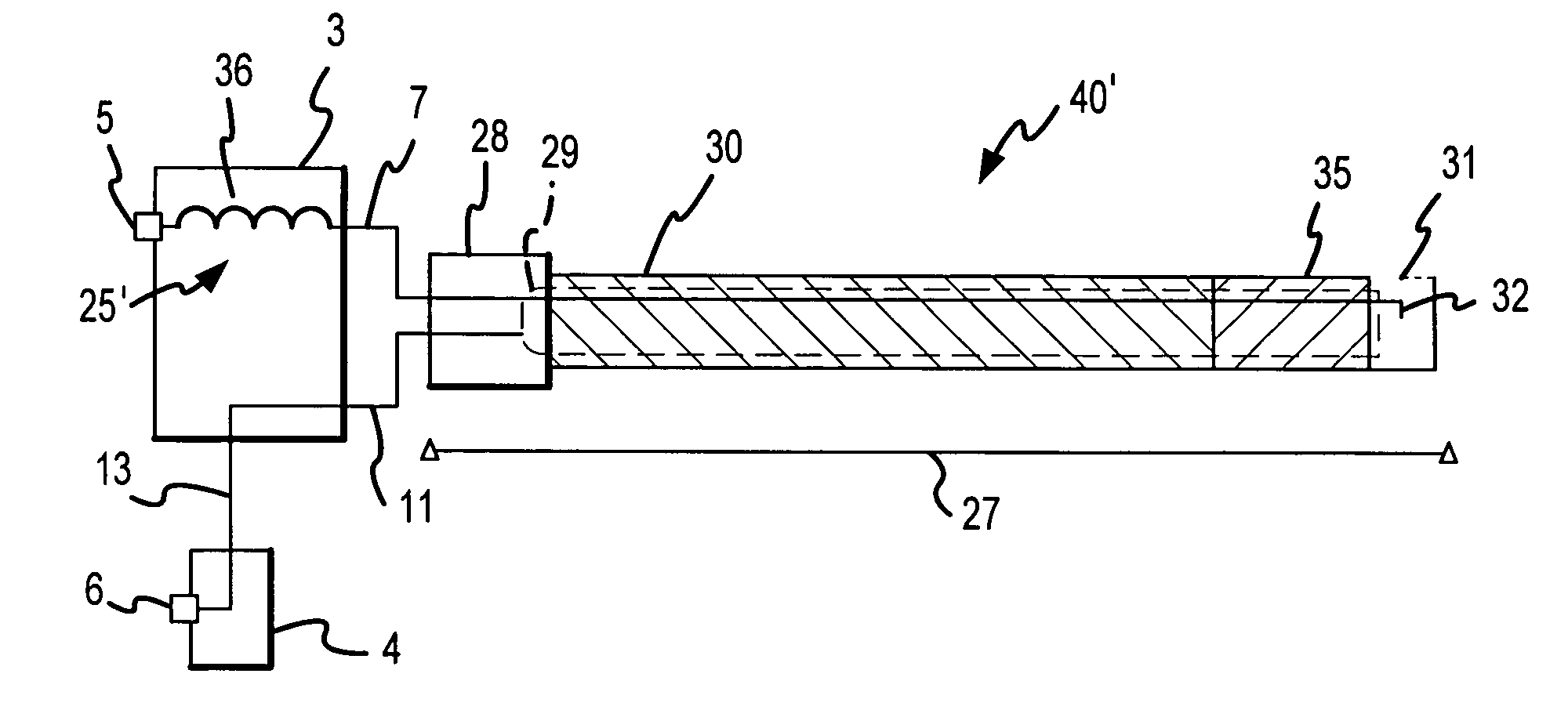
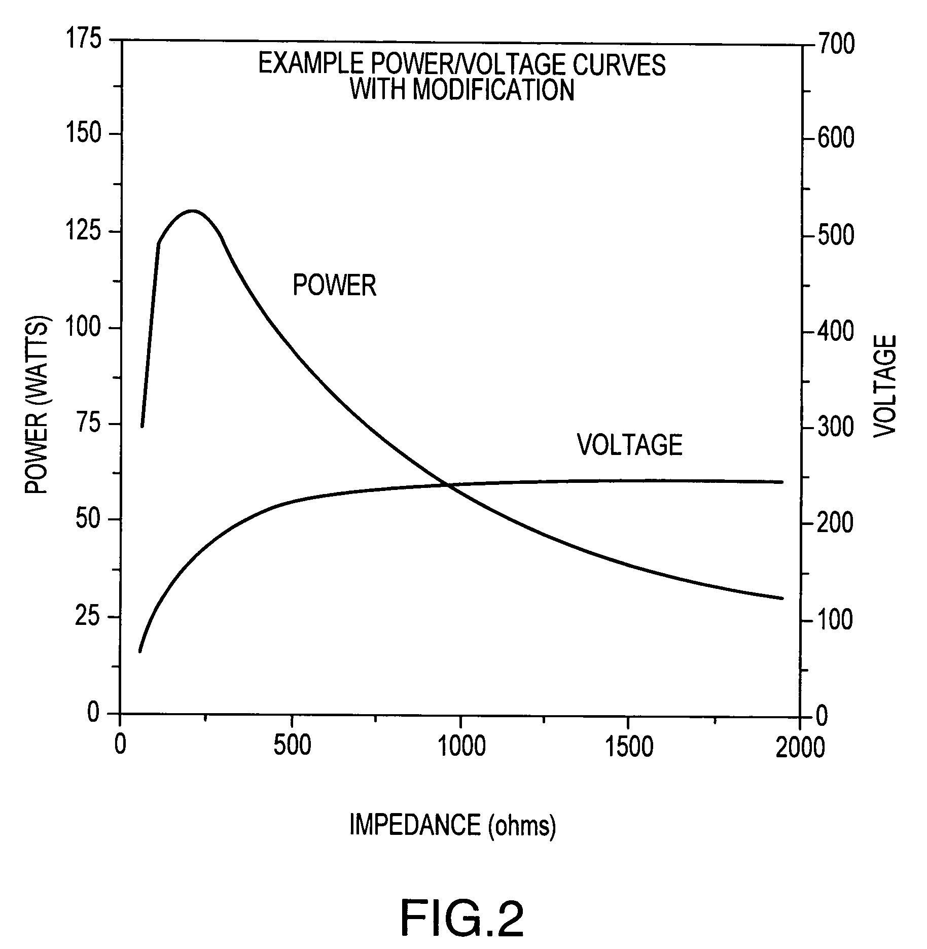
[0020]A first aspect of the present invention allows for limiting a maximum voltage which is applied to a patient during an electrosurgical procedure using an electrosurgical generator and an electrosurgical assembly which is separate from and interfaces with the generator. The electrosurgical generator and electrosurgical assembly are separate components and may be operatively interconnected at the desired time to affect the execution of desired electrosurgical procedure. One particularly desirable application of the subject first aspect is when the electrosurgical generator is of a constant power type configuration, or even more preferably when the electrosurgical generator is operating other than on a constant voltage basis. In this case, the electrosurgical assembly may include one or more relevant components to effectively allow the electrosurgical assembly to execute an at least substantially constant voltage electrosurgical procedure, or stated another way to allow the electrosurgical assembly to deliver voltage at least at substantially a constant magnitude to the patient. This is desirable for a number of reasons, including for reducing the potential for tissue damage.
[0060]Special features may exist in the port connections on the electrosurgical generator. A common feature on electrosurgical generators is for one or more control wires to extend from the accessory to the power plug and from there to one or more additional connectors and jacks in the generator. These control wires connect to one or more switches in the accessory, typically in the handle, and allow the user to activate the generator and have it deliver power. Another common feature is for the return path device in the form of a monopolar return electrode pad to have two wires leading from it to the return plug and for the return plug to connect to a jack having two conductive contacts. The two conductive paths are used to implement features that measure the contact impedance between the return pad and the patient's skin to determine whether adequate contact exists to avoid unintentional burns where the return pad is applied to the skin. These additional conductive paths may be routed so that they pass through a single plug, such as the power plug, to reduce the number of cables leading to an accessory, such as a bipolar device.

Problems solved by technology

Electrosurgical procedures can experience inadvertent problems that lead to unintended tissue damage.
Such inadvertent energy application can lead to burns or other complications.
When surgical instruments are being inserted or withdrawn from patients during MIS procedures, concern exists for inadvertent activation of the RF energy source and tissue damage that could occur from such an event.
One aspect of this problem occurs when the return path device is positioned such that it causes high current flux through tissue adjacent to it.
High current flux can cause tissue burns or other damage.
It would be desirable for the devices used by surgeons to not allow such inadvertent high current fluxes to occur.
Constant power can lead to runaway interactions between the RF energy and the tissue.
This increased voltage will lead to continued changes in the tissue with corresponding increases in tissue impedance, which, in turn, cause the generator to increase the voltage further.
The cycle of events usually occurs very rapidly, so rapidly that during some procedures it is beyond the user's ability to respond quickly and prevent undesired tissue effects such as charring or excessive tissue destruction.
To date, the advantages of constant voltage cannot be easily obtained from constant power generators.
U.S. Pat. No. 5,472,443 also presents a means for retrofitting selected generators to modify the output, however the circuit presented has considerable complexity and does not lend itself to use in disposable products.

Method used


Image

  • Electrosurgical mode conversion system
  • Electrosurgical mode conversion system
  • Electrosurgical mode conversion system

Examples


Embodiment Construction

[0083]The present invention will now be described in relation to the accompanying drawings which at least assist in illustrating its various pertinent features. This description starts with the output mode conversion circuit that converts the output from a constant power electrosurgical generator to approximately constant voltage. The description then covers the return coupler. The final description covers the output mode conversion circuit in conjunction with the return coupler.

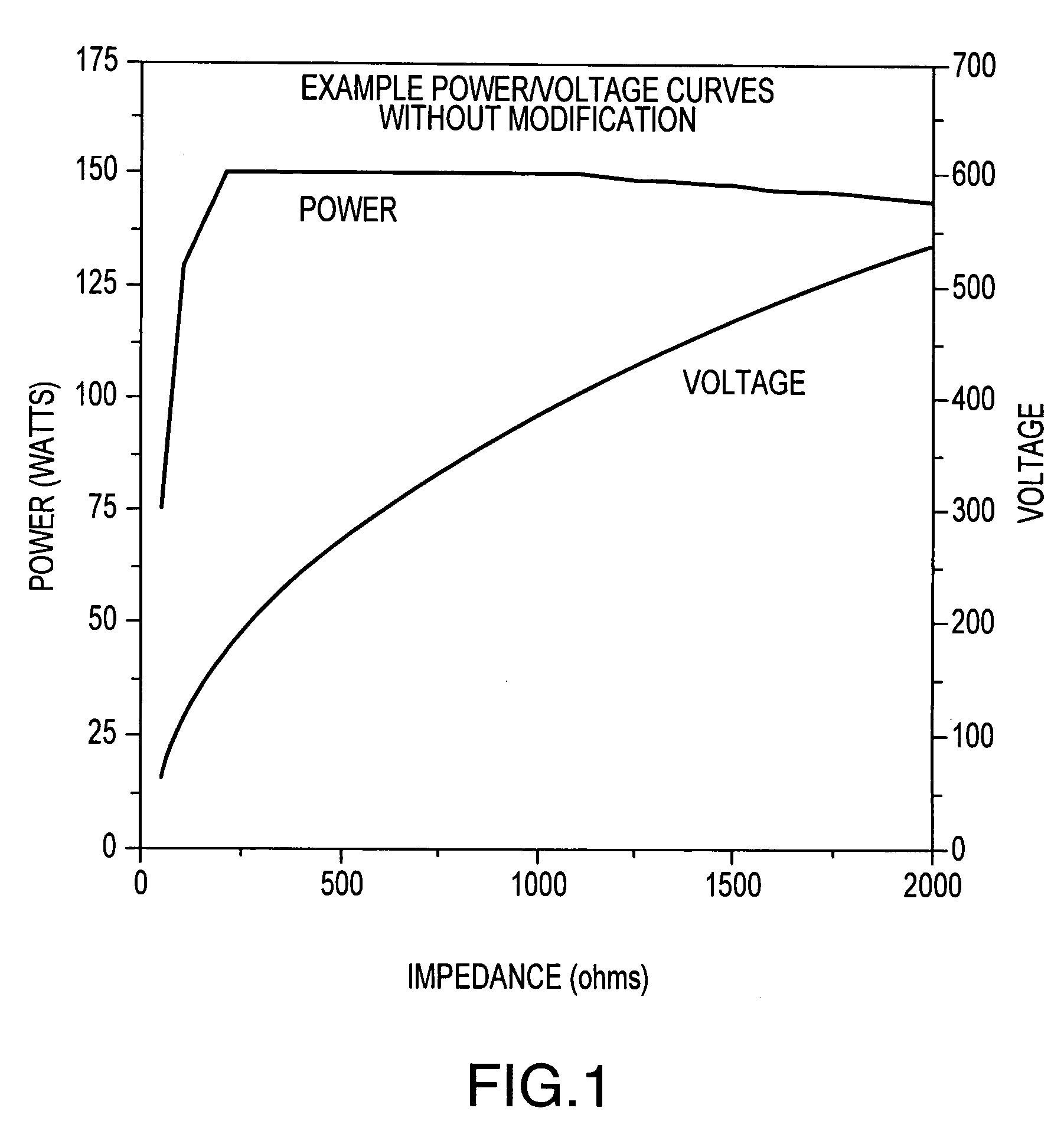
[0084]FIG. 1 illustrates the power and voltage outputs from a modern electrosurgical generator that produces approximately constant power. As the load impedance increases, the voltage produced increases. The power shown is the average power in watts and the voltage shown is RMS voltage. Test measurements indicate what impedances are expected. Typical patient load impedances during, for example, arthroscopic ablation, are about 1,700 ohms and range during use from about 1,000 to about 4,500 ohms. The voltage ...


PUM

PropertyMeasurementUnit
dielectric constantaaaaaaaaaa

Abstract

A surgical system that applies electrical energy to obtain predetermined surgical effects while improving the control of the application of the energy that is supplied by electrosurgical generators. In one embodiment, a surgical assembly interfaces with and receives power from an electrosurgical generator for executing a first electrosurgical procedure. This surgical assembly may employ a shunt circuit between its power and return lines for providing in effect a voltage limitation and / or to allow a constant power electrosurgical generator to execute an at least substantially constant voltage electrosurgical technique. The electrosurgical assembly may also include a return coupler for directing energy from the patient back to the electrosurgical generator, which in turn may include a dielectric material which interfaces with the patient and which at least initially conveys the return energy via one or more electric fields versus conduction.

Description

RELATED APPLICATIONS[0001]This patent application claims priority under 35 U.S.C. §119(e) to U.S. patent application Ser. No. 60 / 144,946, that was filed on Jul. 21, 1999, that is entitled “SURGICAL MODE CONVERSION SYSTEM,” the entire disclosure of which is incorporated by reference in its entirety herein, and further is a divisional of, and claims priority under 35 U.S.C. §120 to, U.S. patent application Ser. No. 09 / 619,919, that was filed on Jul. 20, 2000 now U.S. Pat. No. 6,692,489, that is entitled “ELECTROSURGICAL MODE CONVERSION SYSTEM,” and the entire disclosure of which is also incorporated by reference in its entirety herein.FIELD OF THE INVENTION[0002]The present invention relates to surgical methods and assemblies employing the application of electrical energy to tissue to achieve a predetermined surgical effect, and, more particularly, to achieve such effect with reduced likelihood of inadvertent tissue damage and with better control of energy application to tissues.BACKG...

Claims


Application Information

Patent Timeline
Patent Type & Authority Patents(United States)
IPC IPC(8): A61B18/18A61B18/12A61N1/06A61B18/14
CPCA61B18/12A61B18/1206A61B18/14A61B18/1233A61B2018/00892A61B2018/00178A61B2018/0066A61B2018/00779A61B2018/00119
Inventor HEIM, WARREN P.BRASSELL, JAMES L.OLICHNEY, MICHAEL D.
Owner MICROLINE SURGICAL INC
Learn More