
Graft delivery system

Inactive Publication Date: 2007-02-13
DEPUY ACROMED INC
View PDF157 Cites 48 Cited by
  • Summary
  • Abstract
  • Description
  • Claims
  • Application Information

AI Technical Summary

Benefits of technology

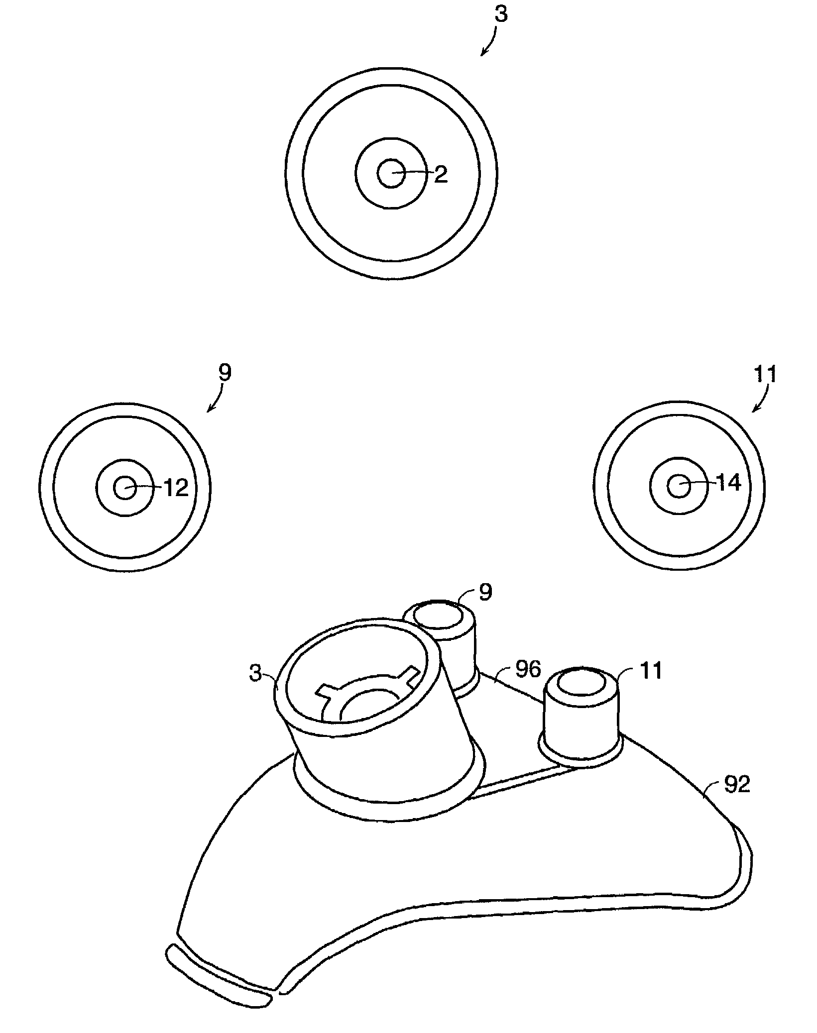
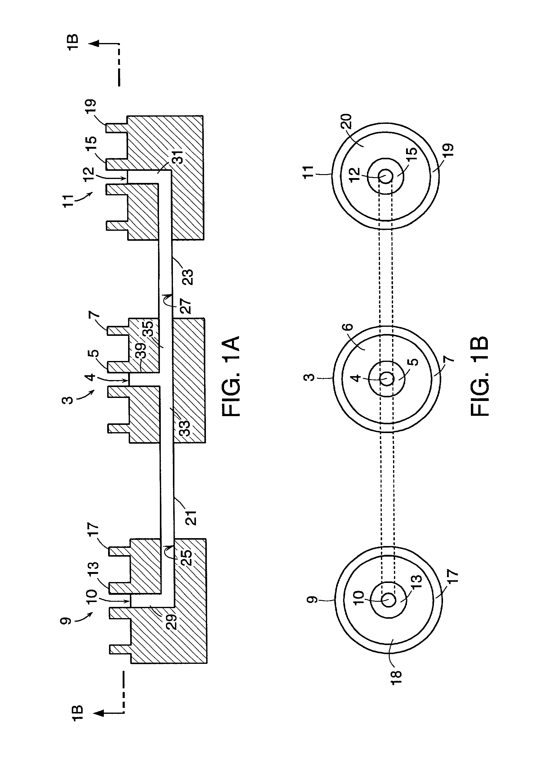
[0014]In one embodiment of the invention, the present invention comprises a manifold suitable for delivering PRP and thrombin to a fluid retention chamber, wherein the manifold comprises only two input ports. By providing only two input ports, the operating procedure is simplified because there is no need for the surgeon to open and close valves. Dedication also reduces the possibility of intra-manifold clotting.

Problems solved by technology

Dedication also reduces the possibility of intra-manifold clotting.

Method used


Image

  • Graft delivery system
  • Graft delivery system
  • Graft delivery system

Examples


example i

[0178]In some cases, the surgeon may choose to use autograft (i.e., bone from the patient) as a source of matrix cells and bone growth factor to complement the growth factors in the platelets in the PRP precursor and accelerate the bone growth process. Therefore, in one preferred embodiment, and now referring to FIG. 25, the graft chamber 412 having an attached funnel 307 is placed on a stand 304 (step1), and the barrel of the chamber is filled with graft materials such as bone particles through the funnel 307 (step 2). The bone graft may be optionally tamped, if desired. Next, lid 306 is placed on the funnel 307 (step 3), and the chamber syringe is inverted and shaken in order to homogeneously distribute the bone particles (step 4). The syringe is then re-inserted into the stand (step 5), the lid is removed, and the bone graft is tamped into the syringe (step 6). At this point, the funnel is removed (step 7), and the syringe is removed from the stand (step 8). Next, the end cap cap...

example ii

[0181]In some cases, the surgeon may choose to use allograft (i.e., bone from another human source) as a source of bone, matrix and growth factors in addition to autograft from the patient. In this example, the syringe is prefilled with bone graft (allograft), and so initially has end caps. The prefilled syringe is placed upon stand and the upper end cap is replaced with a funnel. The remaining steps, beginning with step 3, of example I are followed.

example iii

[0182]In some cases, the surgeon may choose to simply use allograft (bone from another human source). In this embodiment, the syringe is prefilled with bone graft (allograft), and so initially has two end caps. An end cap is replaced with a manifold connector, and the prefilled syringe is then placed in a stand. Once the second end cap is removed, and the delivery syringes are also placed in the manifold, the remaining steps of example I are followed.


PUM

PropertyMeasurementUnit
Angleaaaaaaaaaa
Angleaaaaaaaaaa
Angleaaaaaaaaaa

Abstract

The invention relates to a manifold for mixing biomedical fluids having superior stability and minimal susceptibility to clotting.

Description

BACKGROUND OF THE INVENTION[0001]When a posterior or posterior-lateral fusion of selected spinal facet joints is desired, the surgeon may seek to enhance the fusion of these joints by placing a gel compound comprising graft material (such as autograft bone chips) and platelet-rich plasma (“PRP”) alongside the spinal ridges adjacent to the facet joints. The autograft bone chips contain matrix molecules and living cells such as osteoblasts, and the platelets in the PRP contain additional growth factors which facilitate fusion.[0002]Procedures have been developed for producing this gel. For example, in one conventional process for making the bone chip / platelet-containing gel, the bone chips are placed in a small petri dish, and a 10:1 volumetric mixture of PRP and thrombin (a coagulation agent) is sprayed onto the bone chips. The fibrinogen in the PRP reacts with the thrombin to form clot-producing fibrin, thereby forming a clotted gel. Although this conventional process has been adopt...

Claims


Application Information

Patent Timeline
IPC IPC(8): B01F3/10A61M39/00B01F15/02B01F23/47A61B17/00A61F2/00A61F2/28A61F2/44A61F2/46A61J1/00A61J1/20
CPCA61F2/4644A61F2/4601A61F2/4455A61F2/4405A61F2002/2835A61F2002/30713A61F2250/0087A61J1/2096A61J2001/2031A61J2001/2037A61J2001/2055A61J2001/2058A61J2001/2062A61J2001/2075A61B2017/00495A61J1/2055A61J1/2075A61J1/2062A61J1/2031A61J1/2037A61J1/2058A61F2002/3071
Inventor VOELLMICKE, JOHN C.CONNOLLY, STEPHEN W.KADIYALA, SUDHAKARBRUDER, SCOTT P.URBAHNS, DAVIDTANAKA, KAZUNAKAPEC, JEFFREYNAOI, YUKIKO
Owner DEPUY ACROMED INC
Learn More