
Service panel with utility controller

Inactive Publication Date: 2005-02-10
ISIMET MAPA
View PDF4 Cites 24 Cited by
  • Summary
  • Abstract
  • Description
  • Claims
  • Application Information

AI Technical Summary

Benefits of technology

[0027] Object and advantages of the present invention include: providing an accessible service panel with a logic controller containing the major components needed for the control of the various services typically utilized in school science classrooms; providing a service panel with a logic controller where the components are pre-selected and pre-assembled to insure compatibility in the installation and further permitting ease in the installation process; and providing a service panel with a logic controller having the means to insure the safety of the students occupying the classroom.
[0035] Also, because the service panel and utility controller contain pre-wired components with disconnect switches, there is ease in maintenance.

Problems solved by technology

Access to the interior region is limited such as, for example, by a cover with a keyed lock.

Method used


Image

  • Service panel with utility controller
  • Service panel with utility controller
  • Service panel with utility controller

Examples


Embodiment Construction

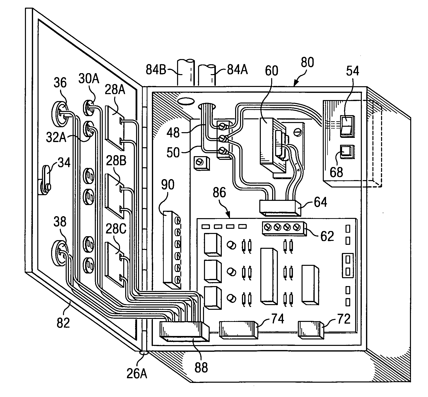
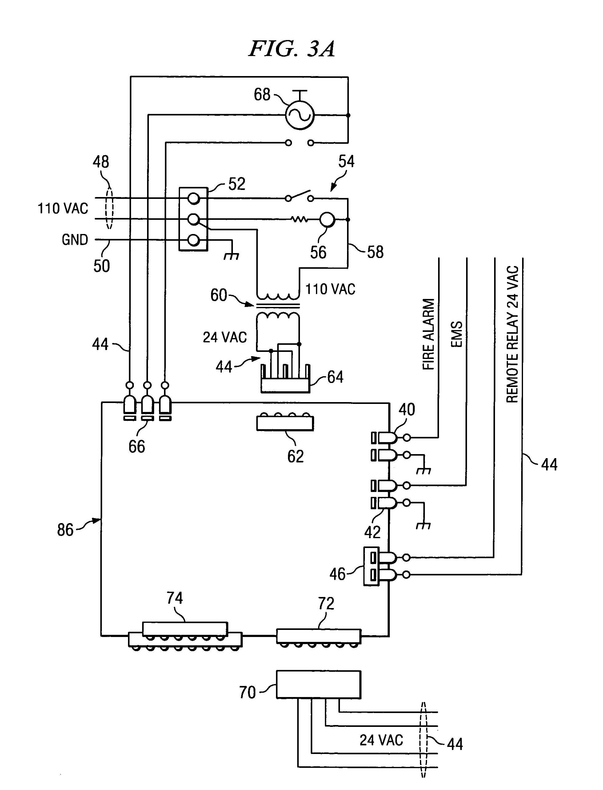
[0058] The invention is a service panel having an integrated utility controller for controlling the various services typically utilized in a science classroom, such as for example, only shown in FIGS. 2, 8, 9, 11, 16, 18, and 19. The panel, doors and other containment components are preferably constructed of welded sheet metal, and contain the various components needed for the control of selected utilities.

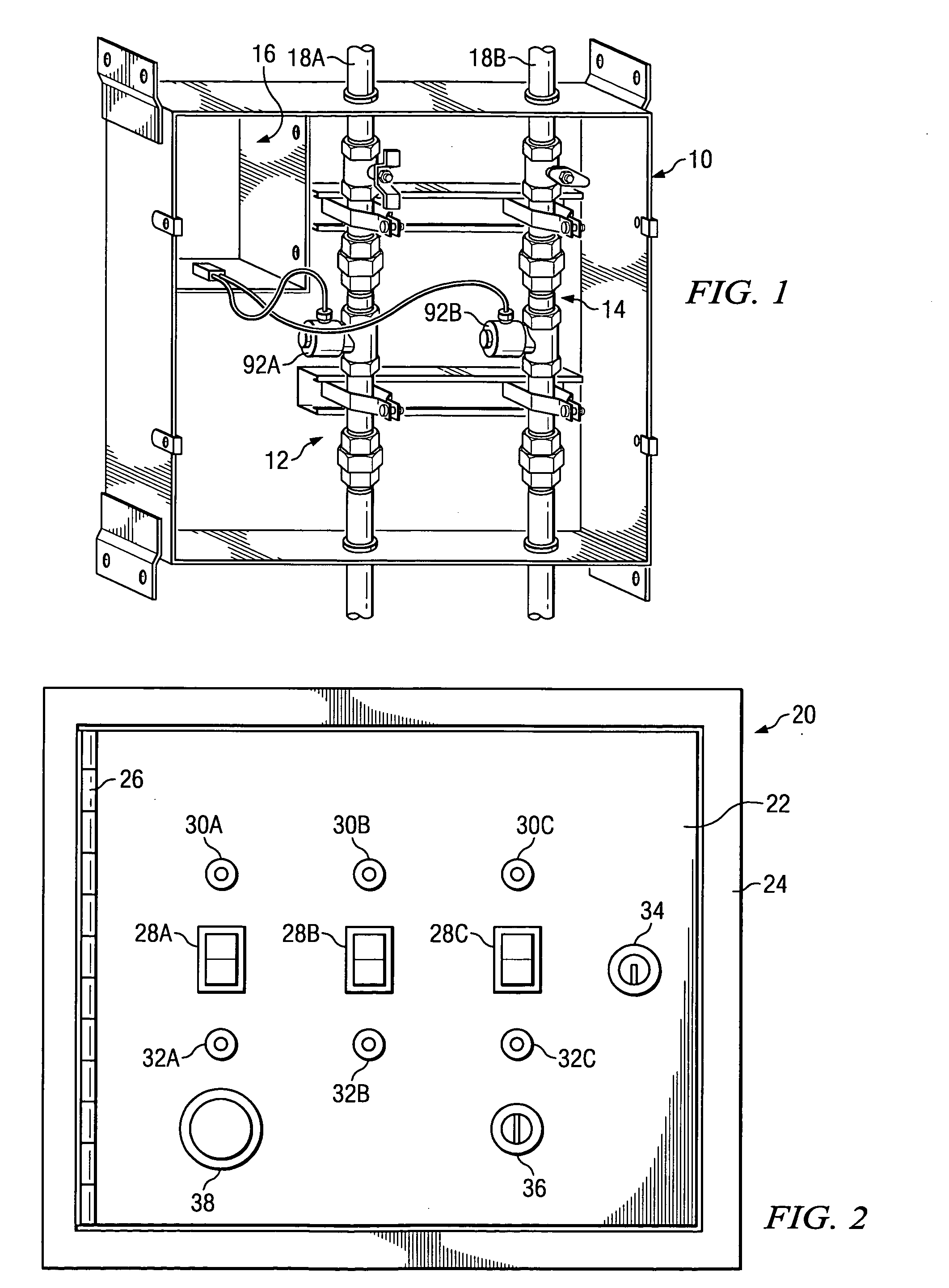
[0059] As shown in FIG. 1, and according to one embodiment, the interior of the service panel 10 houses the water cut-off valve 12 and the gas cut-off valve 14. A utility controller is positioned in the upper left hand portion area 16 of the service panel. The entry points of service piping 18A and 18B into the panel 10 are preferably sealed airtight.

[0060] Now turning to the door panel assembly, FIG. 2 shows a plane frontal view of door panel assembly 20. In the illustrated embodiment door panel 22 is affixed to doorframe 24 with a continuous hinge 26. On the surface of the doo...


PUM


Abstract

A utility controller and a service panel combination for limiting access to authorized persons. A sub-region of the service panel contains at least one electrically-operated (e.g., solenoid-operated) valve that is connected to service utilities (e.g., water or gas) piping so as to control flow there-through. According to one embodiment, another sub-region (i.e., a utility controller region) contains electrical controls for controlling the valve(s) and communicating with other services such as a remote transmitter, or an auxiliary monitoring system (e.g., a fire alarm system). In another embodiment, the service panel is remotely located with respect to the utility controller. The controller facilitates provision of numerous features including: emergency shutdown by anyone while permitting reset only by authorized personnel; modular construction so as to facilitate installation of the system. Various jumper terminals and connecting wires provide for programming of the system to accommodate a variety of applications.

Description

[0001] This application claims the benefit of prior filed co-pending U.S. application Ser. No. 10 / 310,491, filed on Dec. 5, 2002, U.S. application Ser. No. 09 / 662,522, filed on Sep. 14, 2000, and U.S. Provisional Application No. 60 / 155,179 filed on Sep. 21, 1999, which applications are incorporated herein by reference.BACKGROUND OF THE INVENTION [0002] This invention relates to controlling utility services within buildings and more particularly to the logical control of such utility services. [0003] Logical control of utility services within buildings has heretofore been proposed, illustrative of which are the proposals of U.S. Pat. No. 5,267,587 granted to Geoffrey P. Brown on Dec. 7, 1993 and U.S. Pat. No. 5,331,619 granted to Thomas G. Barnum, et al. on Jul. 19, 1994. [0004] In the fields of plumbing and electrical, it is typically required that various services within building structures be provided with a means of control so that individual areas receiving these services can be...

Claims


Application Information

Patent Timeline
IPC IPC(8): F16K37/00
CPCF16K37/0075Y10T137/86389
Inventor PARKER, PHIL A.
Owner ISIMET MAPA
Learn More