
Vertical slide clip

Inactive Publication Date: 2007-02-13
CLARKWESTERN DIETRICH BUILDING SYST
View PDF34 Cites 51 Cited by
  • Summary
  • Abstract
  • Description
  • Claims
  • Application Information

AI Technical Summary

Benefits of technology

[0008]To achieve the foregoing and other objects, and in accordance with one aspect of the present invention, an improved bracket for connecting a pair of substantially perpendicular building components is provided. The bracket of the present invention advantageously allows relative vertical movement between the perpendicular building components. Preferably, the bracket includes a first connector plate joined at an edge and aligned with a second connector plate in substantially a right angle to form a right-angled juncture.
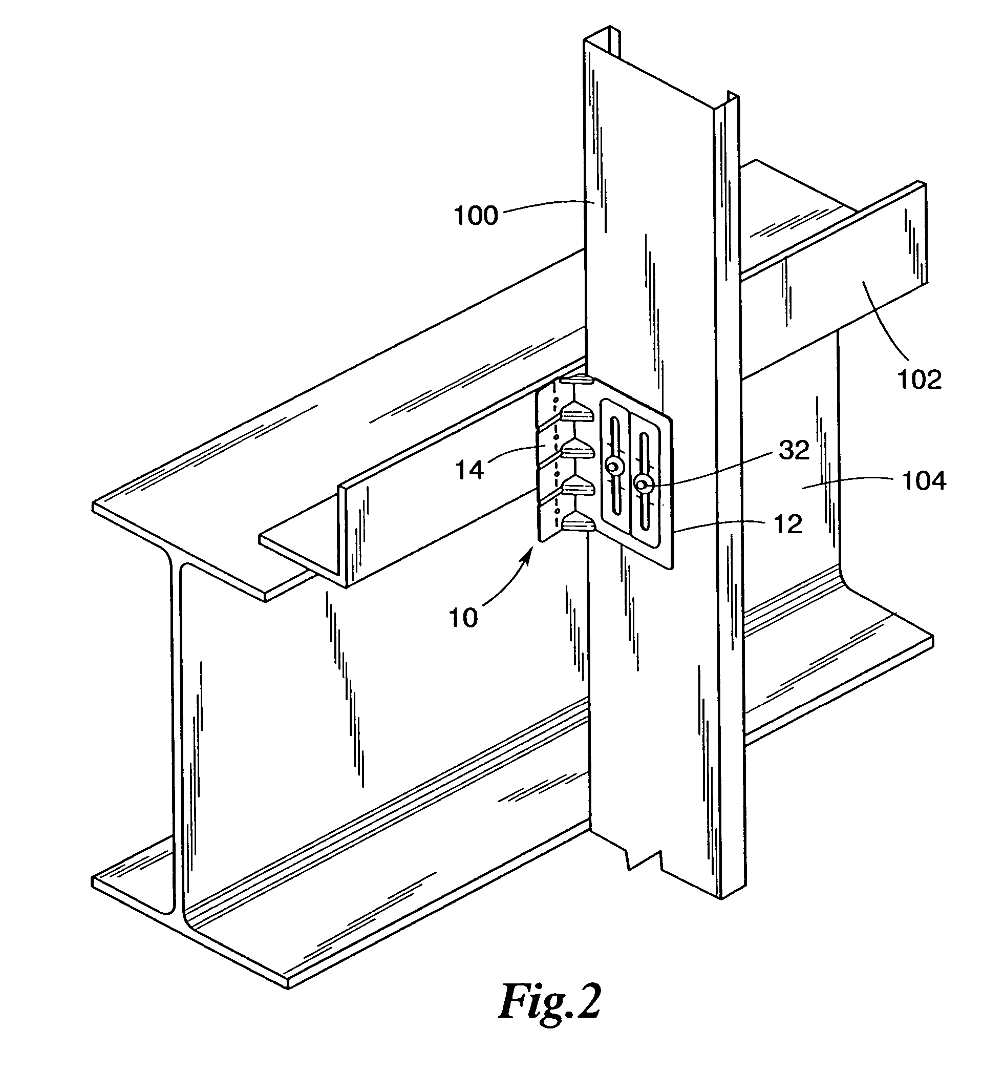
[0010]The second plate includes a number of elongated slots through which the plate may be connected with a shoulder crew or the like to a building component. The slot allows for vertical movement of the building structure without transferring compressive loads to the building component connected to the second plate, such as an exterior curtain wall. The first plate may be connected to structural framing of the building. When the structural framing of the building flexes downward, the bracket of the present invention allows for relative vertical movement thus relieving stresses and eliminating and resisting horizontal forces caused by wind or seismic loads.

Problems solved by technology

In addition to the occurrence of wind induced or seismic stress loading of a building structure, building component deflection is caused by changes in live or dead loading of the floor below or the ceiling above the curtain wall.
When such a building structure is stressed, curtain walls tend to be damaged and the degree of damage sustained by other building parts is also increased.

Method used


Image

  • Vertical slide clip
  • Vertical slide clip
  • Vertical slide clip

Examples


Embodiment Construction

[0021]Reference will not be made in detail to the present preferred embodiments of the invention, examples of which are illustrated in the accompanying drawings wherein like numerals indicate corresponding elements throughout the figures.

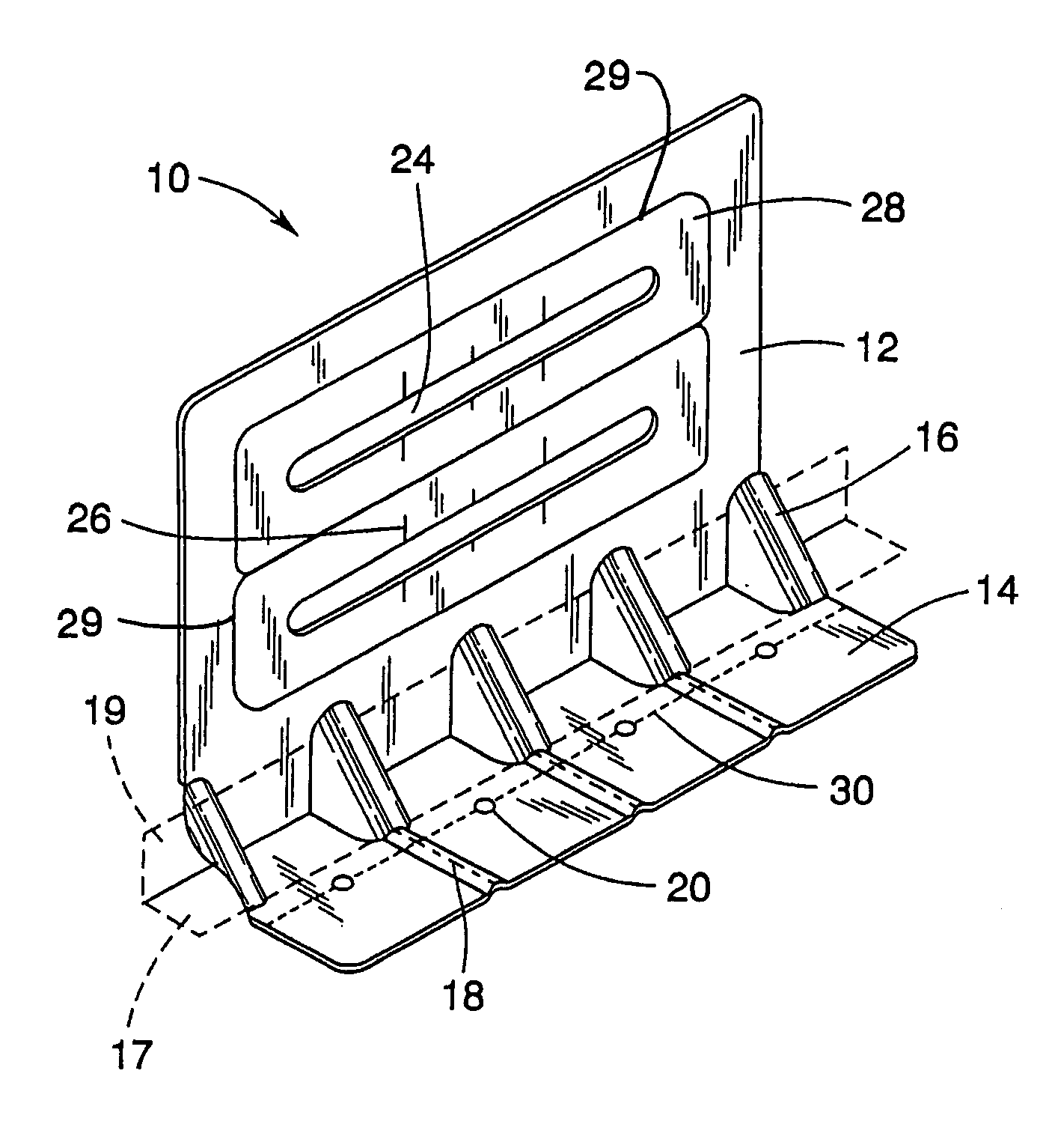
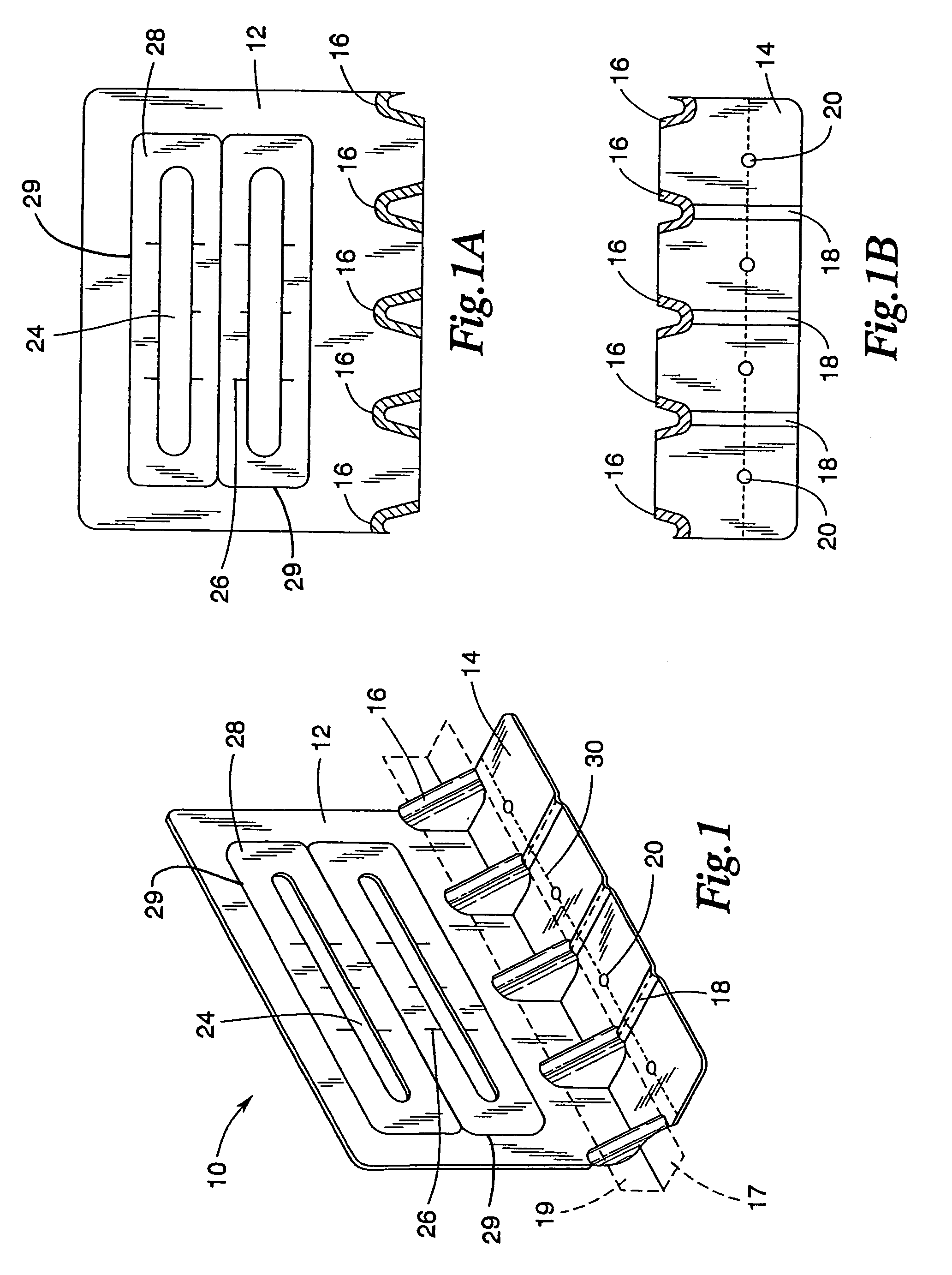
[0022]FIG. 1 illustrates generally at 10 a preferred embodiment of the bracket of the present invention. Bracket 10 is preferably comprised of a stiff, durable, and thin material such as galvanized sheet steel. Preferably, the bracket 10 of the present invention is comprised of 14-gauge sheet steel having a thickness of about 0.07 inches. Depending on the need of the given construction environment, it should be appreciated that the thickness of the bracket 10 may be of essentially any commercially available sheet steel regardless of gauge or thickness. As best seen in FIG. 1, the bracket 10 includes a substantially planar first connector plate 14 and a substantially planar second connector plate 12. As seen in FIG. 1, the first connector plate 14 an...


PUM


Abstract

Brackets for interconnecting building components. One bracket embodiment is constructed to connect a pair of substantially perpendicular building components so as to allow relative vertical movement between those components and may include a first connector plate and a second connector plate. The first and second connector plates may be integrally connected at a right angle so as to form a right angled juncture. A plurality of stiffener channels may be disposed in the right angle juncture. The bracket may further include a plurality of substantially linear stiffener channels formed in the first connector plate. One or more elongated slots may be provided in the second connector plate. In another embodiment, one or more rows of holes are provided in the connector plate. The elongated slots or rows of holes may be located in one or more recessed stiffener regions. A score line and / or dimples may be provided in the first connector plate for locating fasteners.

Description

CROSS REFERENCE TO RELATED APPLICATIONS[0001]This application is a continuation application of U.S. patent application Ser. No. 09 / 912,098 to Rahim Allagheband Zadeh, filed Jul. 24, 2001 now U.S. Pat. No. 6,688,069 and entitled Vertical Slide Clip and which claims the benefit of U.S. Provisional Patent Application Ser. No. 60 / 220,420, filed Jul. 24, 2000.TECHNICAL FIELD[0002]This invention relates to steel stud building systems, and, more particularly to brackets for connecting vertical steel wall studs to a building structure in a manner to permit relative vertical movement but prevent relative horizontal movement therebetween.BACKGROUND OF THE INVENTION[0003]Many industrial and commercial buildings and an increasing number of residential buildings are being constructed with steel stud wall systems for the various benefits obtained, such as reduced environmental concerns, fire safety and reduced susceptibility from warpage, insects, rust and rot.[0004]In the construction of buildin...

Claims


Application Information

Patent Timeline
IPC IPC(8): E04B1/38E04C5/00E04B1/24
CPCE04B1/2403E04B2001/2415E04B2001/405E04B2001/2448E04B2001/2439E04B2001/389
Inventor ZADEH, RAHIM ALLAGHEBAND
Owner CLARKWESTERN DIETRICH BUILDING SYST
Learn More