
Optical fiber cable

a technology of optical fiber and fiber cable, which is applied in the direction of optical waveguide light guide, fibre mechanical structure, instruments, etc., can solve the problems of low viscosity of uncured matrix resin composition, inability to bring the curing time to not less than 10 min, and inability to achieve high flexibility of glass fiber reinforced resin tension members, etc., to achieve excellent bending properties and flexibility, excellent bending properties

Inactive Publication Date: 2007-01-30
HITACHI CABLE
View PDF11 Cites 250 Cited by
  • Summary
  • Abstract
  • Description
  • Claims
  • Application Information

AI Technical Summary

Benefits of technology

The solution provides an optical fiber cable with enhanced flexibility and bending properties, reduced curling, and improved handling characteristics, while ensuring high curing speed and low viscosity for efficient resin penetration, and preventing adverse gas evolution during processing.

Problems solved by technology

AS compared with tension members formed of a glass fiber reinforced resin, however, these tension members are disadvantageous in that the minimum bending diameter (a limit diameter which causes a fracture of the tension member upon bending in an arc form) is large and the level of the so-called “curling,” which is such a phenomenon that, when the tension member is wound around a bobbin and rewound for use, the tension member is curved to a level corresponding to the winding diameter of the bobbin, is large.
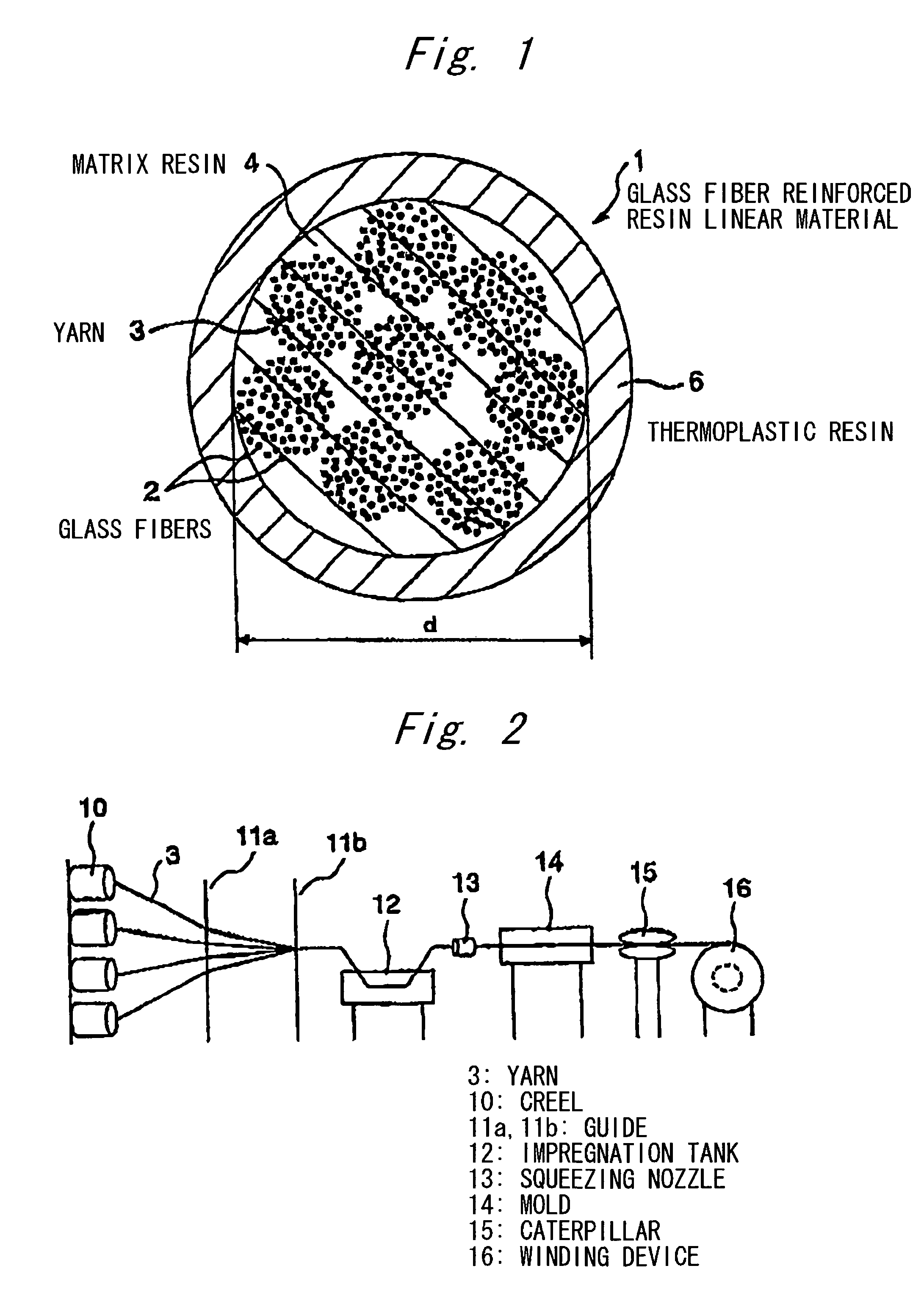
However, none of tension members formed of a glass fiber reinforced resin have such a high level of flexibility that the minimum bending diameter D is less than 20 times the diameter d of the glass fiber reinforced resin linear material.
From the viewpoint of the size of the mold and production equipment, however, the curing time cannot be brought to not less than 10 min.
Further, the viscosity of the uncured matrix resin composition is desirably low.
This is because, when the viscosity of the resin composition is high, the penetration of the resin composition into gaps between glass fibers is difficult.
When the glass fibers are finer, the penetration of the resin composition into yarns of a plurality of glass fibers is more difficult.
Furthermore, the use of tension members using an unsaturated polyester resin or a vinyl ester resin as the matrix resin sometimes poses a problem in post processing as an optical fiber cable.

Method used


Image

  • Optical fiber cable
  • Optical fiber cable
  • Optical fiber cable

Examples


examples

[0132]The invention will be explained in more detail with reference to the following examples. However, the invention is not limited to these examples only.

examples 1 to 3

[0133]High-strength glass fibers sold by Nitto Boseki Co., Ltd. (tradename “T-GLASS,” elongation at break 0.5.5%, modulus of elasticity 84.3 GPa) were provided. T-GLASS contained 65% by weight of SiO2, 23% by weight of Al2O3, 11% by weight of MgO, and less than 1% by weight of ZrO2. Detailed specifications of the high-strength glass fibers are shown in Table 1.

[0134]

TABLE 1ElasticFiberTensilemodulus inElongationProductCountTreatmentdiameterDensitystrengthtensionat breakRST28280 g / kmEpoxysilane7 μm2.49 g / cm34.65 GPa84.3 GPa5.5%PA-535treatment

[0135]Expoxy resin produced in the presence of a thermal cationic polymerization catalyst was used as matrix resin. Formulations of Examples 1 to 3 are shown in Table 2.

[0136]

TABLE 2ComponentEx. 1Ex. 2Ex. 3(1)CELLOXIDE 2021P804056(2)CELLOXIDE 2081—4024(3)Epikote 1002202020(4)SD551101010(5)SI-100L111(6)ST86PA (antifoaming agent)0.010.010.01

[0137]CELLOXIDE 2021P and CELLOXIDE 2081, which are liquid epoxy resin, were obtained from Daicel Chemical In...

examples 4 and 5

[0146]The dimension of a mold was changed according to the combination of the matrix resin with the glass fibers in Example 3 to mold a glass fiber reinforced resin composition having an outer diameter of 0.42 mm (Example 4) and a glass fiber reinforced resin composition having an outer diameter of 0.51 mm (Example 5). In the same manner as in Examples 1 to 3, the minimum bending diameter was measured and was found to be 7.0 mm and 9.0 mm which were respectively 16.7 times and 17.6 times larger than the diameter of the linear materials.


PUM

PropertyMeasurementUnit
elongation at breakaaaaaaaaaa
viscosityaaaaaaaaaa
mode field diameteraaaaaaaaaa

Abstract

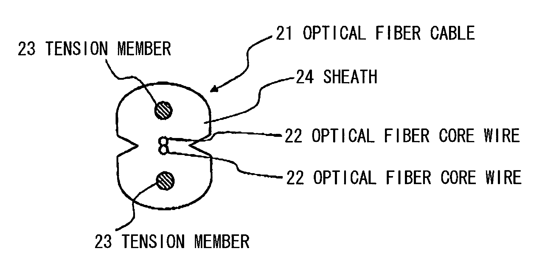
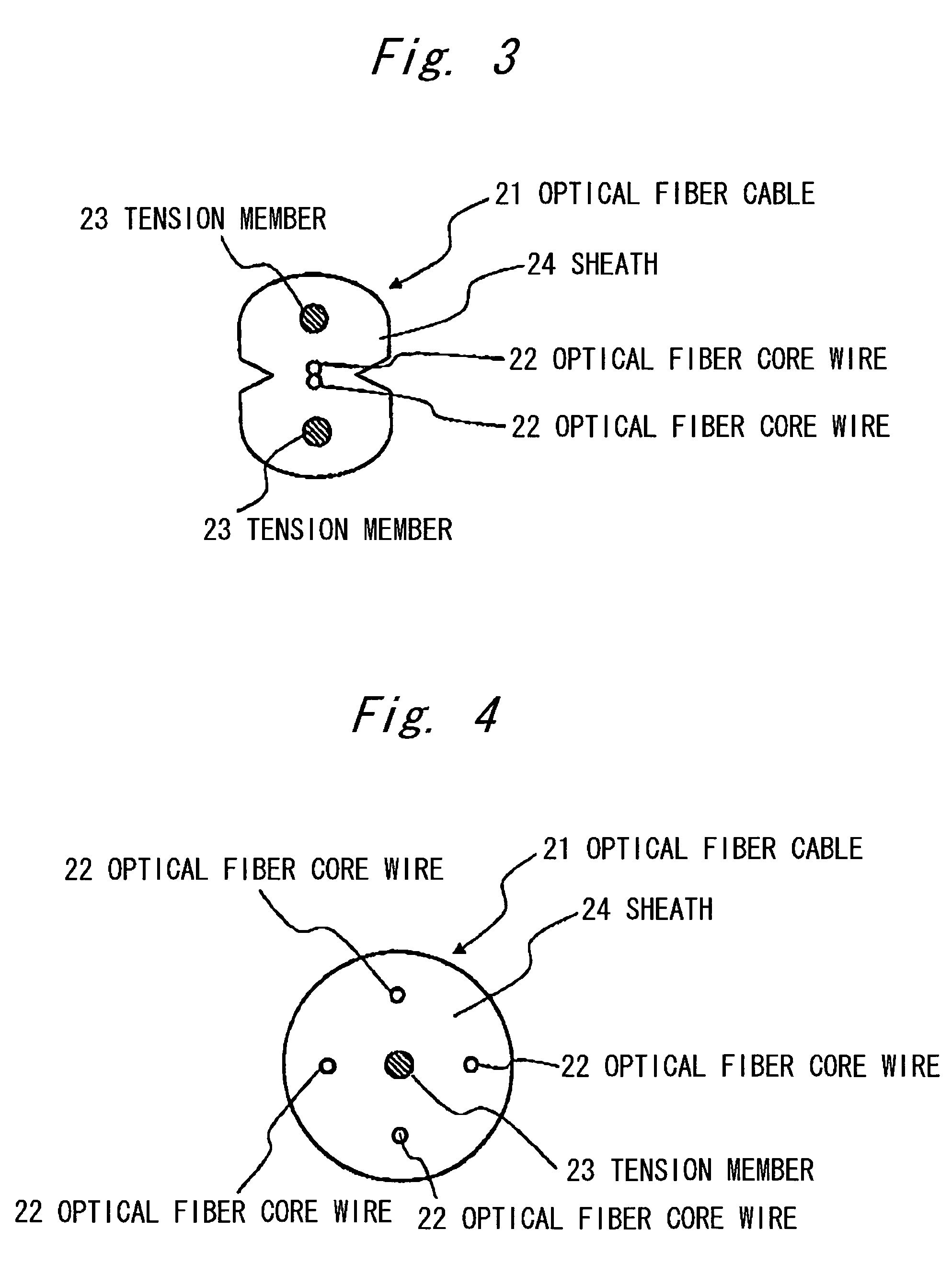
An optical fiber cable has an optical fiber core wire and a tension member. The tension member is formed of a glass fiber reinforced resin linear material with glass fibers and a matrix resin, and satisfies the following requirements: (1) (EfVf+EmVm)d2≧8.3 / n wherein Ef represents the modulus of elasticity of glass fibers, GPa; Vf represents the content of glass fibers, % / 100; Em represents the modulus of elasticity of matrix resin, GPa; Vm represents the content of matrix resin, % / 100; d represents the diameter of tension member, mm; and n represents the number of tension members used in optical fiber cable; (2) (Ef / Em)≧22; (3) Vf=0.6 to 0.88; and (4) an elongation at break of glass fibers of not less than 5% and an elongation at break of matrix resin of not less than 5%.

Description

[0001]The present application is based on Japanese patent application No. 2004-094047, the entire contents of which are incorporated herein by reference.BACKGROUND OF THE INVENTION[0002]1. Field of the Invention[0003]The invention relates to an optical fiber cable. More particularly, the invention relates to an optical fiber cable using a tension member comprising organic or inorganic reinforcing fibers.[0004]2. Description of the Related Art[0005]An optical fiber cable is a cable comprising a plurality of converged optical fibers and has become rapidly widely used, for example, in offices and large apartments in Japan. In the optical fiber cable, tension members are used for preventing the optical fibers from being elongated to a level beyond the specified limit. Such optical fiber cables are described, for example, in Japanese Patent Laid-Open Nos. 15000 / 2003, 241681 / 2000, 107307 / 2003, and 23925 / 1999, Utility Model Registration No. 2503790, and Japanese Patent Laid-Open Nos. 19984...

Claims


Application Information

Patent Timeline
Patent Type & Authority Patents(United States)
IPC IPC(8): G02B6/44
CPCG02B6/4432
Inventor TAKAHASHI, YOSHIHIRO
Owner HITACHI CABLE
Learn More