
Electrophotographic image forming apparatus having a plurality of mounting portions for detachably mounting a plurality process cartridges

a technology of electrotrophotographic image and forming apparatus, which is applied in the direction of electrographic process, optics, instruments, etc., can solve the problem of taller apparatus

Inactive Publication Date: 2007-01-16
CANON KK
View PDF9 Cites 134 Cited by
  • Summary
  • Abstract
  • Description
  • Claims
  • Application Information

AI Technical Summary

Benefits of technology

[0010]Another object of the present invention is to provide an electrophotographic image forming apparatus superior to an image forming apparatus in accordance with the prior art in terms of operational efficiency in mounting a process cartridge into the main assembly of the image forming apparatus, and dismounting it therefrom.
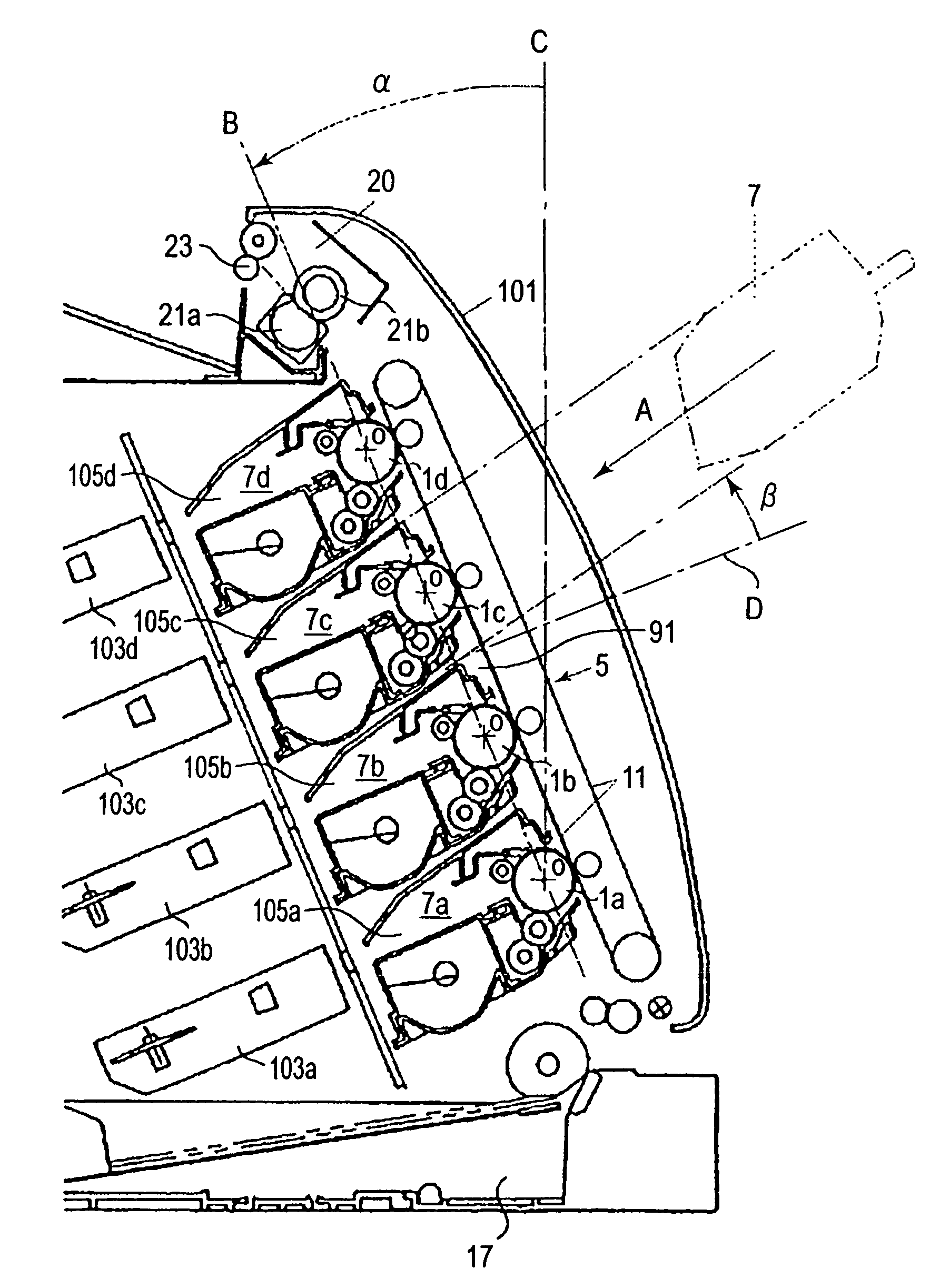
[0011]Another object of the present invention is to provide an electrophotographic image forming apparatus having a plurality of process cartridge compartments in which a plurality of process cartridges are removably mountable, one for one, and which are stacked in such a manner that a hypothetical plane which coincides with the axial lines of the photosensitive drums of the plurality of process cartridges in the cartridge compartments of the main assembly is tilted downward relative to the vertical line, as seen from the upstream side, in terms of the direction in which the process cartridges are mounted into the main assembly of the electrophotographic image forming apparatus, so that an operator can mount the plurality of process cartridges into the main assembly, or remove them therefrom with substantially greater operational efficiency than a plurality of process cartridges can be mounted into or removed from a main assembly of an electrophotographic image forming apparatus in accordance with the prior art.
[0012]Another object of the present invention is to provide an electrophotographic image forming apparatus having a plurality of process cartridge compartments in which a plurality of process cartridges are removably mountable, one for one and which are stacked in such a manner that a hypothetical plane which coincides with the axial lines of the photosensitive drums of the plurality of process cartridges in the cartridge compartments of the main assembly is tilted downward relative to the vertical line, as seen from the upstream side, in terms of the direction in which the process cartridges are mounted into the main assembly of the electrophotographic image forming apparatus, so that an operator can mount the plurality of process cartridges into the plurality of cartridge compartments of the main assembly, or remove them therefrom, in the direction tilted upward from the plane perpendicular to the above-mentioned plane substantially improving the operational efficiency with which a plurality of process cartridges can be mounted into or removed from the main assembly of an electrophotographic image forming apparatus as compared to the prior art.

Problems solved by technology

A vertical tandem design, however, is likely to make the apparatus taller.

Method used


Image

  • Electrophotographic image forming apparatus having a plurality of mounting portions for detachably mounting a plurality process cartridges
  • Electrophotographic image forming apparatus having a plurality of mounting portions for detachably mounting a plurality process cartridges
  • Electrophotographic image forming apparatus having a plurality of mounting portions for detachably mounting a plurality process cartridges

Examples


embodiment 1

(1) General Structure of Electrophotographic Color Image Forming Apparatus

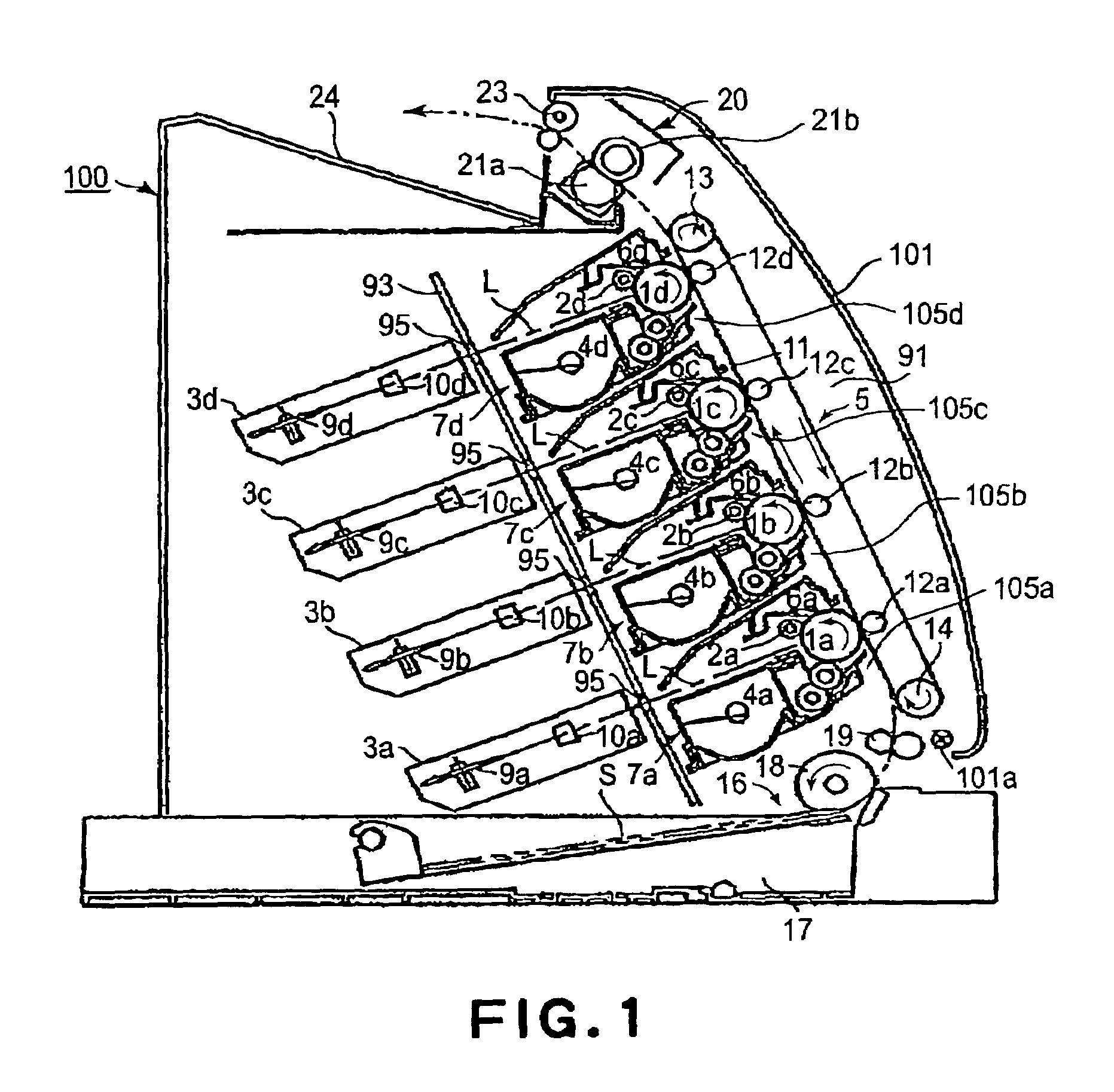
[0030]FIG. 1 is a schematic vertical sectional view of the electrophotographic image forming apparatus (electrophotographic color image forming apparatus) which is used with the first to fourth process cartridges mounted therein. This apparatus is an electrophotographic full-color laser beam printer. It employs a transfer system and a vertical tandem system, and is designed to be used with a plurality of process cartridges removably mounted in the main assembly thereof.

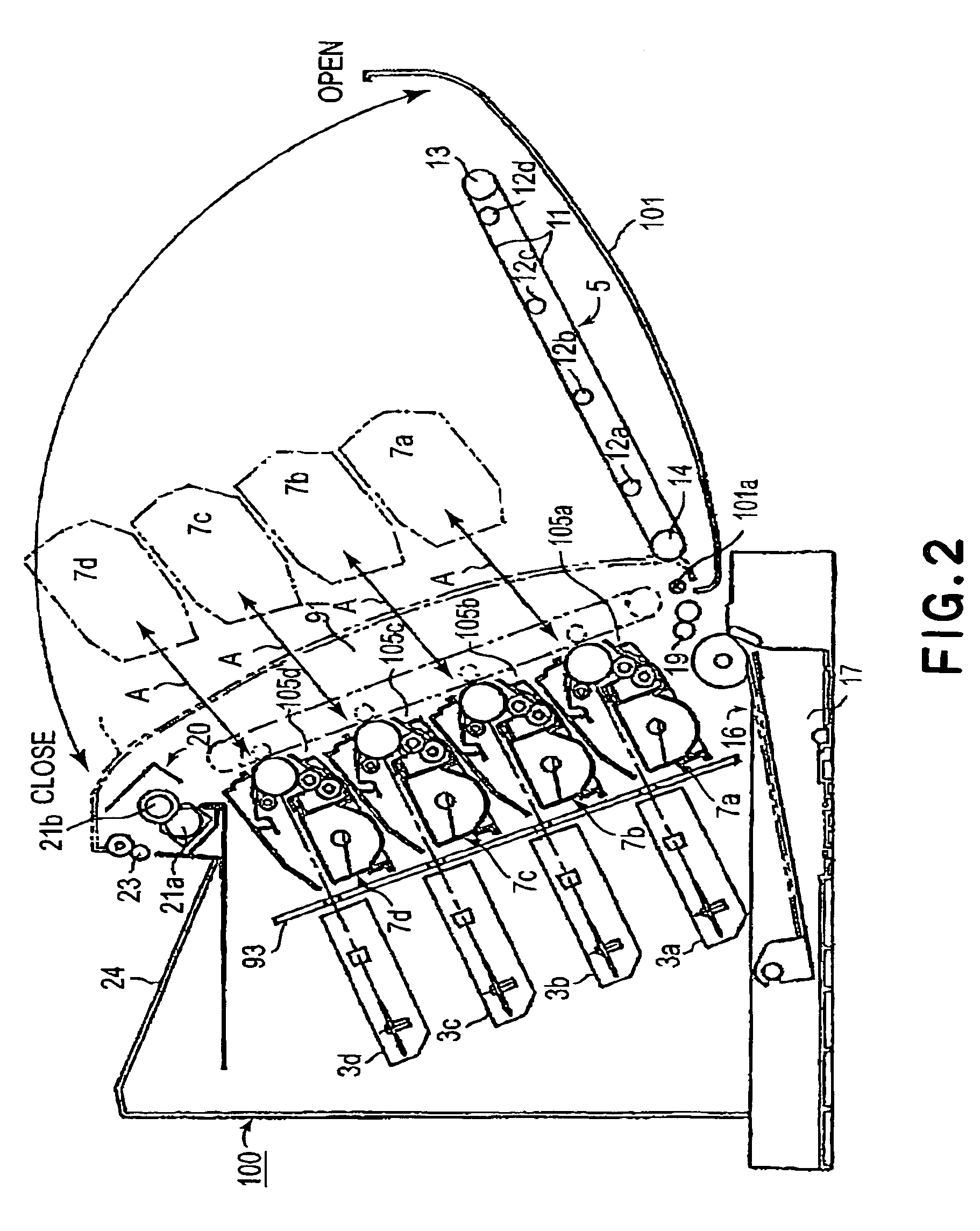
[0031]The main assembly 100 of the image forming apparatus (which hereinafter will be referred to simply as the main assembly) has a front door as a hinged member (which hereinafter will be referred to as the front door) 101 which is rotatably opened toward an operator, or closed away from the operator, about the hinge 101a located at the bottom edge of the door 101. In other words, the hinged front door 101 is attached to the upstream side of t...

embodiment 2

[0080]Next, referring to FIGS. 10 and 11, the second embodiment of the present invention will be described. The components, members, portions, etc., in this embodiment, which are the same as those in the first embodiment, are given the same referential symbols as those given in the first embodiment, and will not be described here.

[0081]The image forming apparatus 200 in this embodiment is virtually the same in structure as that in the first embodiment, except that the apparatus main assembly 200 in this embodiment is structured so that the beam of laser light L projected from each of the scanner units 103(a–d) to expose the peripheral surfaces of the photosensitive drums 1(a–d) of the corresponding cartridges 107(a–d) enters the corresponding cartridge 7(a–d) at an upward angle relative to the plane D1 which is perpendicular to the aforementioned plane B and coincides with the axial line of the photosensitive drum 1. Reference symbols La–Ld designate the paths of the beams of laser ...


PUM


Abstract

An electrophotographic image forming apparatus usable with process cartridges. The apparatus includes mounting portions for detachably mounting the cartridges. In each mounting portion, a cartridge is inclined downwardly from an upstream to a downstream side with respect to a mounting direction and a phantom plane passing through axes of the drums is inclined toward a downstream side with respect to the mounting direction from a bottom part to a top part of the phantom plane. Parts of cartridges mounted to a lower one and the next higher one of the mounting portions overlap, as seen along a plane perpendicular to the phantom plane from an upstream side with respect to the mounting direction. The apparatus also has a light projector and a feeder for feeding recording material, and the cartridges are mounted to or demounted from respective mounting portions from above the perpendicular plane.

Description

FIELD OF THE INVENTION AND RELATED ART[0001]The present invention relates to an electrophotographic image forming apparatus which forms images by employing a plurality of process cartridges removably mounted in the main assembly of the apparatus.[0002]As for the examples of the above-mentioned electrophotographic image forming apparatus, there are an electrophotographic copying machine, an electrophotographic printer (for example, a laser beam printer, an LED printer, etc.), a facsimile machine, a word processor, etc.BACKGROUND TECHNOLOGIES[0003]As an electrophotographic color image forming apparatus in accordance with the prior art, a color image forming apparatus of the so-called tandem type has been known, in which four process cartridges for forming toner images of cyan, magenta, yellow, and black colors, one for one, are vertically stacked in parallel, virtually in a straight line. A tandem type color image forming apparatus is designed so that the developing devices of the plu...

Claims


Application Information

Patent Timeline
Patent Type & Authority Patents(United States)
IPC IPC(8): G03G21/16G03G21/18
CPCG03G21/1839G03G2221/1884
Inventor MIYABE, SHIGEOTOBA, SHINJIROUENO, TAKAHITO
Owner CANON KK
Learn More