
Snowmobile front suspension system and method

a front suspension and snowmobile technology, applied in the direction of children's carriages/perambulators, sledges, vehicle components, etc., can solve the problems of increasing the difficulty of appropriately and functionally designing the area of the vehicle, affecting the ski rate, so as to achieve the effect of increasing the ski ra

Active Publication Date: 2005-09-13
POLARIS IND INC
View PDF35 Cites 87 Cited by
  • Summary
  • Abstract
  • Description
  • Claims
  • Application Information

AI Technical Summary

Benefits of technology

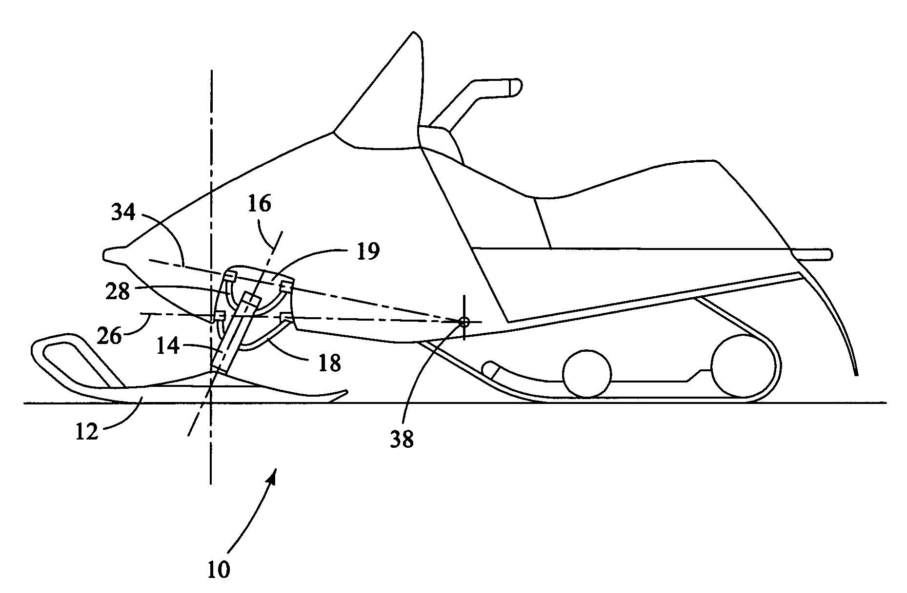
[0006]The present invention in one embodiment provides a snowmobile having a longitudinal axis and a chassis, a pair of skis each having a steering spindle defining a steering axis, and a suspension system joining each steering spindle to the chassis. Each suspension system comprises a first control arm pivotally mounted to the chassis for pivotal movement about a first pivot axis and having a first connection to the spindle and a second control arm pivotally mounted to the chassis for pivotal movement about a second pivot axis and having a second connection to the spindle spaced from the first connection. The pivot axis of each control arm and the connection of that control arm to the spindle defines a control arm plane, and the control arm planes for each ski intersect to define a control line that intersects a vertical plane containing said longitudinal axis. The structure enables such performance characteristics as changes in caster upon compression of the suspension to be adjusted.
[0008]In certain embodiments, the control arms of each ski suspension are so oriented that as the suspension of a snowmobile at rest is compressed toward a fully compressed condition from a partially compressed condition to mimic the compression due to roll as the snowmobile is steered into a tight turn, the camber angle of the ski is moved in the negative direction. In other embodiments, one of the control arms is positioned generally beneath the other, and the suspension system for each ski includes a shock absorber mounted at one end to the chassis and at the other end to the lower control arm at a point spaced from the chassis and is oriented so that as the suspension system is compressed, the motion ratio of movement of the shock along its axis to the vertical movement of the ski increases to thereby increase ski rate.

Problems solved by technology

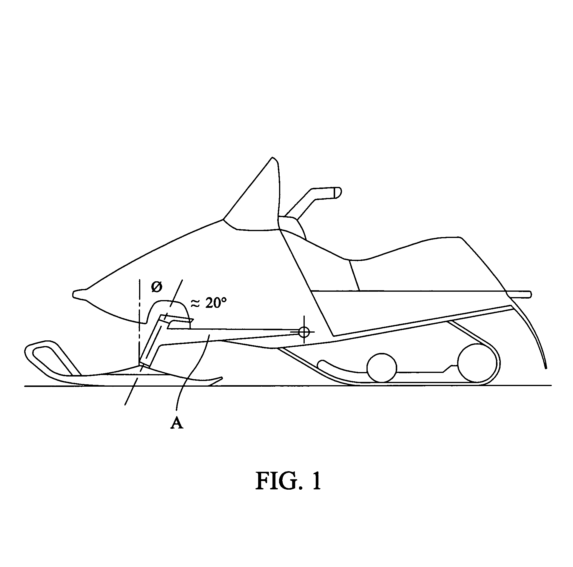
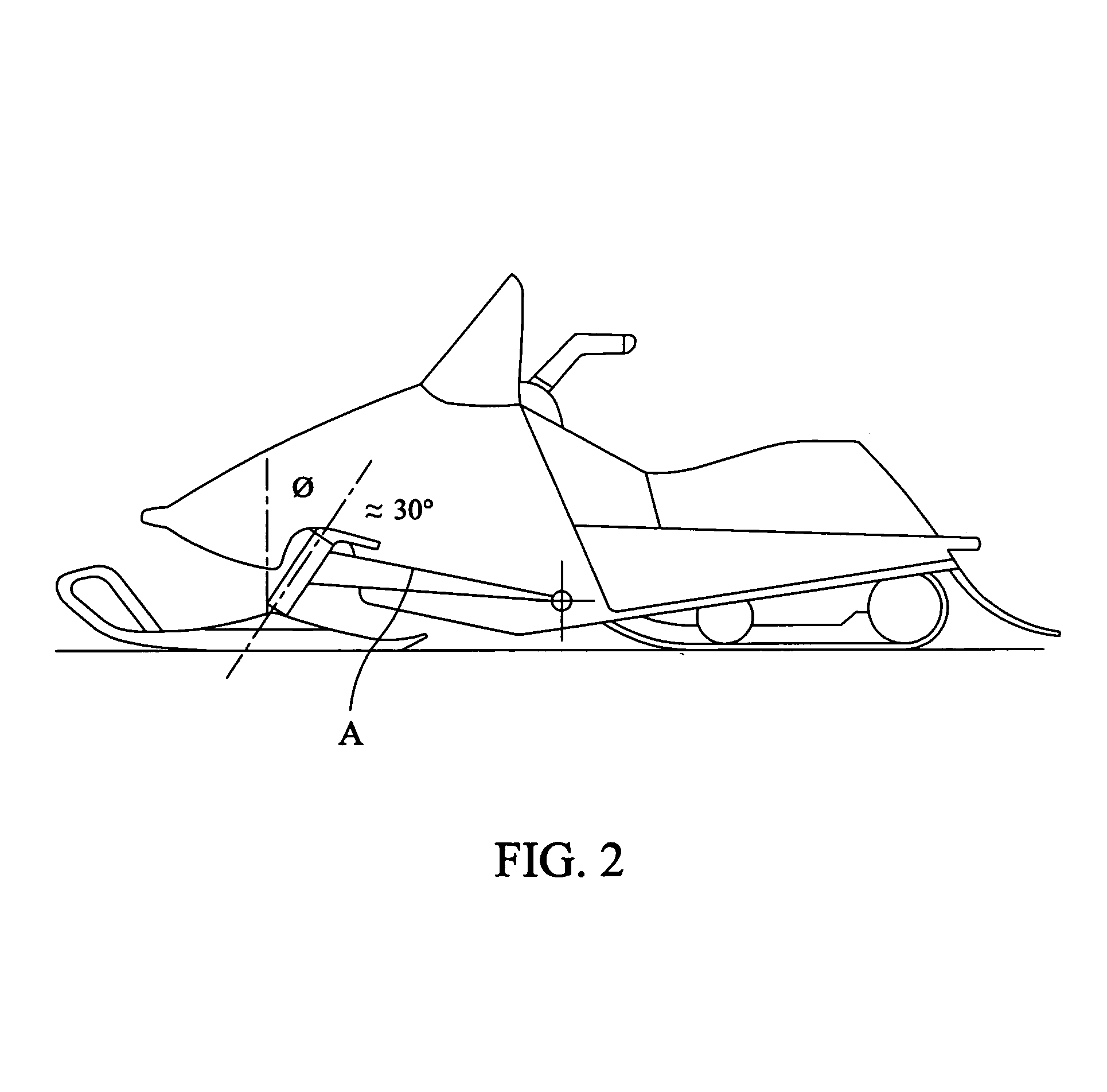
Also, as illustrated in FIGS. 1 and 2 of the drawing, the necessary positioning of the trailing arm takes up space and increases the difficulty of appropriately and functionally designing that area of the vehicle.
Shock absorbers are commonly used for this purpose, and have been commonly mounted in snowmobiles with trailing arm suspensions such that as the suspension is compressed, the compressive axis of the shock absorber becomes less aligned with the generally vertical direction of ski displacement with respect to the chassis, and this leads to the suspension becoming softer as the front suspension is compressed, in turn leading to bottoming-out problems.
That is, the motion ratio of shock absorber movement to vertical ski movement may be reduced as the suspension is compressed, leading to a diminished ski rate.
Not only must one consider the problems raised above in connection with trailing arm suspensions, but also problems involving caster angle and ease of steering and control, problems involving the tendency of a snowmobile to “dive” when braked hard or when encountering obstacles, and problems involving the expected increase in camber angle (and the resulting tendency of the skis to “scrub” or drift sideways) when the chassis of the snowmobile rolls during sharp turns.

Method used


Image

  • Snowmobile front suspension system and method
  • Snowmobile front suspension system and method
  • Snowmobile front suspension system and method

Examples


Embodiment Construction

[0022]A prior art snowmobile utilizing a trailing arm suspension is schematically shown in FIGS. 1 and 2. A trailing arm “A” is pivotally attached at its rearward end to the chassis of the snowmobile, and the forward end of the trailing arm is attached to a housing for the steering spindle of a ski. FIG. 1 shows the snowmobile at rest, with a caster angle Φ between the vertical and the backward leaning steering axis of the ski which may be in the range of 20°. FIG. 2 shows the same snowmobile with its front suspension compressed, as when the snowmobile may hit a bump. Here, the pivotal attachment of the rear-end of the trailing arm to the chassis has moved downwardly, and the caster angle Φ has accordingly become larger, e.g., in the range of 30°, the larger caster angle improving the stability of the snowmobile. Forces directed rearwardly on the trailing arm are transmitted to the chassis at the pivotal connection of the trailing arm with the chassis, and this tends to produce yaw....


PUM


Abstract

The snowmobile having a longitudinal axis, a chassis, a pair of skis each having a steering spindle, and a suspension system. The suspension system comprises, for each ski, a first control arm pivotally mounted to the chassis for pivotal movement about a first pivot axis and having a first pivotal connection to the spindle and a second control arm pivotally mounted to the chassis for pivotal movement about a second pivot axis and having a second pivotal connection to the spindle spaced from the first connection. The pivot axis of each control arm and the connection of that control arm to the spindle define a control arm plane; the control arm planes intersect to define a control line that intersects a vertical plane containing said longitudinal axis.

Description

FIELD OF THE INVENTION[0001]The invention relates to snowmobile front suspension systems.BACKGROUND OF THE INVENTION[0002]A variety of front suspension systems have been employed on snowmobiles over the years. In the early 1980s, the assignee of the present invention introduced to the snowmobiling industry an independent front suspension system utilizing a trailing arm—an elongated arm having its front end rigidly connected to the steering spindle and its rear-end pivotally connected to the chassis. See Canadian Patent No. 1,227,823, and also U.S. Pat. Nos. 6,328,124 and 6,343,666. Front suspension systems employing trailing arms have been widely accepted in the snowmobile industry. When a snowmobile ski encounters an object during operation, the suspension system is designed to permit the ski to travel over the object while providing a relatively smooth, controlled ride to the driver. Some of the force of the perturbance is transmitted by the trailing arm to the chassis, and this i...

Claims


Application Information

Patent Timeline
IPC IPC(8): B62M27/02B62M27/00
CPCB62M27/02B62M2027/026
Inventor HONKALA, BRUCE A.EATON, JEFFREY A.SIBILLEAU, GUY L.BERG, NORMAN O.
Owner POLARIS IND INC
Learn More