
Method of and apparatus for generating a beam of light

Inactive Publication Date: 2007-01-09
ISIS INNOVATION LTD
View PDF8 Cites 8 Cited by
  • Summary
  • Abstract
  • Description
  • Claims
  • Application Information

AI Technical Summary

Benefits of technology

[0009]Accordingly, it is an object of the present invention to provide a method and apparatus for generating a beam of light having extended depth of focus that is efficient and provides a light beam of substantially uniform axial intensity.
[0012]The method makes it possible to generate a light beam with substantially uniform axial intensity and an extended depth of focus. Further, the method is highly efficient, with over 75% of the input light reaching the final focal plane in some cases.
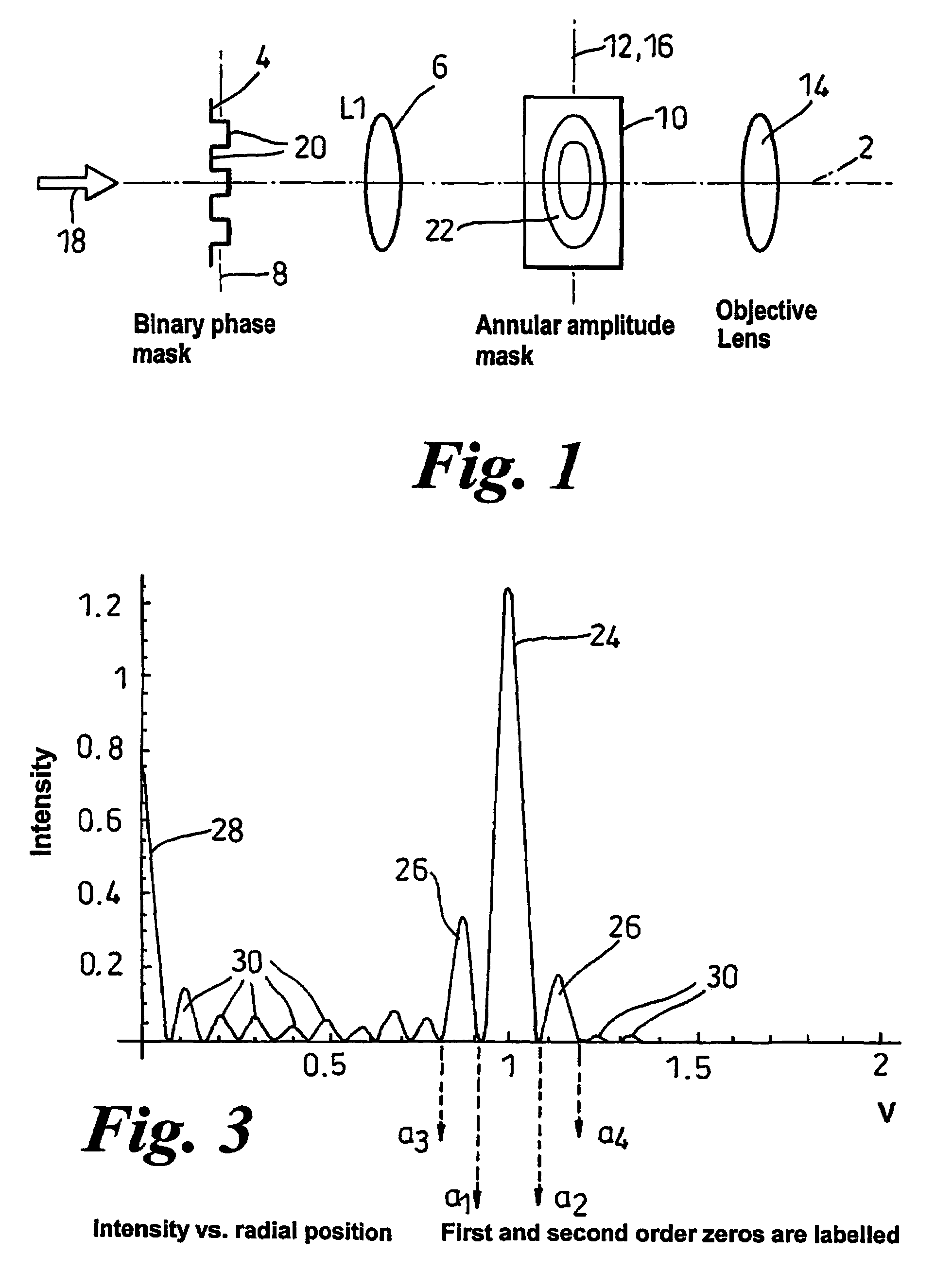
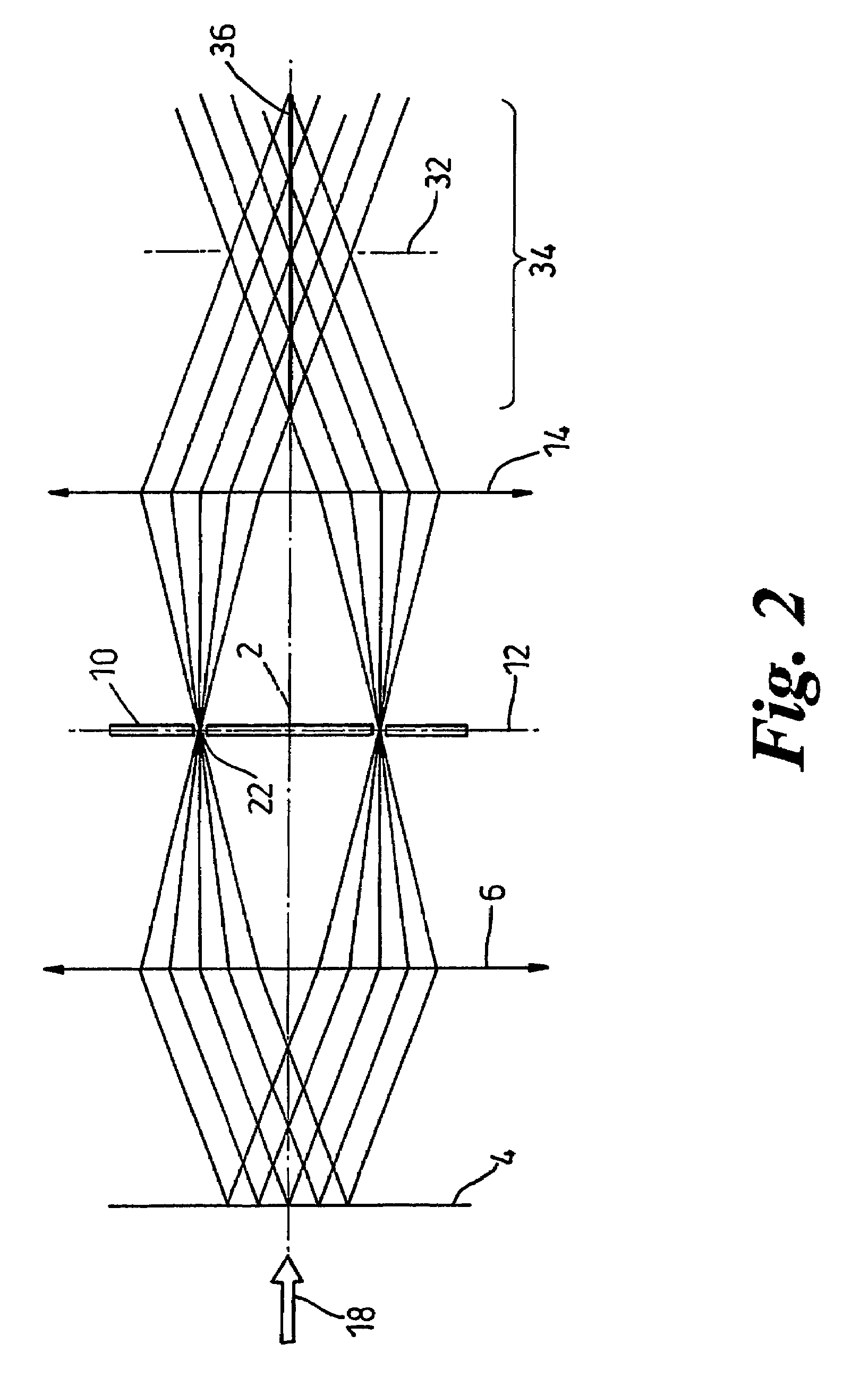
[0024]According to a further aspect of the invention there is provided a method of generating a light beam with an extended depth of focus, the method including generating in a first focal plane a diffraction pattern that includes a bright main ring, modifying the diffraction pattern by means of an annular aperture located in the first focal plane, wherein the radius of the aperture is substantially equal to the radius of the main ring and the width of the aperture is substantially equal to or slightly greater than the width of the main ring, and causing the light passing through the annular aperture to converge towards and cross an optical axis, such that where the converging light crosses the optical axis constructive interference takes place, generating a light beam along said axis that has an extended depth of focus.

Problems solved by technology

Finally, the light passing through the aperture converges toward and crosses an optical axis, such that constructive interference takes place where the converging light crosses the optical axis, thereby generating, along the axis, a beam of light having extended depth of focus.

Method used


Image

  • Method of and apparatus for generating a beam of light
  • Method of and apparatus for generating a beam of light
  • Method of and apparatus for generating a beam of light

Examples


first embodiment

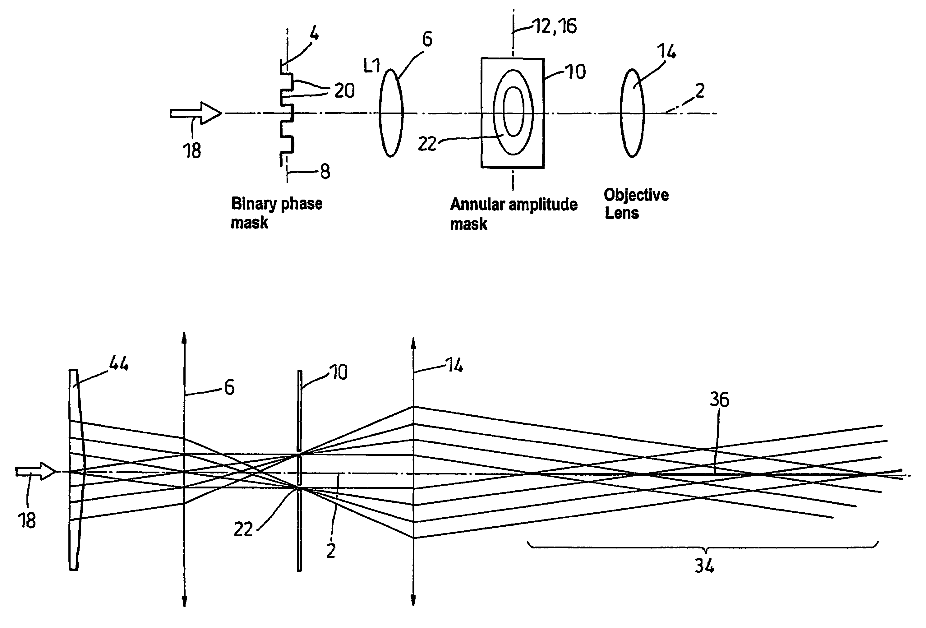
[0039]In the first embodiment, the diffractive element 4 consists of a binary phase mask, comprising a packed series of concentric rings 20 of equal width that impart a relative phase modulation onto the laser beam alternately of 0° and 180°. This is shown in more detail in FIG. 7, in which the grey shade represents a transmission of 0, white a transmission of +1 (a phase of 0°) and black a transmission of −1 (a phase of 180°). Alternatively, an amplitude and phase modulation mask may be used.

[0040]The aperture mask 10, which is shown in FIG. 13, includes an annular amplitude aperture 22 that is located concentrically with the optical axis 2. The factors determining the radius and width of the annular aperture 22 are discussed in more detail below.

[0041]FIG. 2 is a ray diagram illustrating how light passes through the optical system. Collimated homogeneous light from a laser (not shown) enters from the left hand side of the diagram in the direction of the arrow 18 and illuminates th...

second embodiment

[0062]the invention is shown in FIG. 5, in which the diffractive element is replaced by an axicon 44. Collimated homogeneous light from a laser enters from the left hand side of the diagram in the direction of the arrow 18 and illuminates the axicon 44. The light is refracted by the axicon, producing a converging cone of light that is focussed by the first lens 6, producing a pattern that consists essentially of a bright ring 24 in the rear focal plane 12 of that first lens (i.e. in the plane of the aperture mask 10).

[0063]The annular aperture is matched to the width of the main ring 24, so that the whole of the main ring 24 passes through the aperture. The light that passes through the mask 10 is refracted by the objective lens 14, producing a converging cone of light that crosses the optical axis 2.

[0064]In the region 34 where the light crosses the optical axis, constructive interference takes place, producing a very narrow and bright beam of light 36 with substantially uniform ax...


PUM


Abstract

A method and apparatus for generating a beam of light having extended depth of focus. The apparatus comprises, for instance, a binary phase mask that generates a diffraction pattern including a bright main ring and a plurality of side-lobe rings, an annular aperture mask that passing only a portion of the diffraction pattern, and a lens that causes light passing through the annular aperture to converge toward and cross an optical axis. Where the converging light crosses the optical axis, constructive interference takes place, thereby generating a beam of light that has extended depth of focus.

Description

FIELD OF THE INVENTION[0001]The present invention relates generally to optics and, more particularly, to methods and apparatus for for use in microscopy or the like.BACKGROUND OF THE INVENTION[0002]In general, when collimated light is focused, a spot of light is generated having a generally defined axial and lateral extent that is limited by diffraction. An extended depth of focus beam is, by one definition, one in which the axial extent of the focal spot is increased by an arbitrary factor, which is generally greater than 5 but typically less than 20, without significantly compromising the lateral extent. For example, where with a normal lens an axial extent of about 1.5 microns and a lateral extent of approximately 0.5 microns may be achieved, an extended depth of focus beam may have an axial extent of about 15 microns and a lateral extent of about 0.5 microns.[0003]For purposes of the present invention, while the term “light” refers generally to the visible portion of the electro...

Claims


Application Information

Patent Timeline
Patent Type & Authority Patents(United States)
IPC IPC(8): G03B27/42G03B27/54G03B27/72G02B5/00G02B21/06G02B27/46
CPCG02B5/001G02B27/0075G02B21/06
Inventor NEIL, MARKMASSOUMIAN, FARNAZJUSKAITIS, RIMASWILSON, TONY
Owner ISIS INNOVATION LTD
Learn More