Microstrip reflective array antenna adopting a plurality of U-slot patches

a reflective array and microstrip technology, applied in the structural form of individual energised antenna arrays, resonant antennas, radiating elements, etc., can solve the problems of limited signal gain and narrow communication bandwidth, and achieve the effect of substantial thickness, and enhancing the frequency band of microwave signals

Inactive Publication Date: 2007-01-09
TATUNG UNIVERSITY +1
View PDF6 Cites 10 Cited by
  • Summary
  • Abstract
  • Description
  • Claims
  • Application Information

AI Technical Summary

Benefits of technology

[0007]To eliminate the drawbacks of the traditional reflective array antenna, the present invention discloses a microstrip reflective array antenna adopting a plurality of U-slot patches to receive and transmit microwave signals. The microstrip reflective array antenna comprises: a reflective disk for reflecting microwave signals wherein a plurality of square patches are placed on the upper surface of the first substrate, a plurality of U-slot patches are placed on the upper surface of the second substrate, and the lower surface of the first substrate stacking on the upper surface of the second substrate so as to form the reflective disk, and each of the square patches and the U-slot patches corresponds to each other to form an array unit. A horn antenna is adapted to receive and output the microwave signals reflected by the reflective disk. A support is adapted to stabilize the horn antenna directly above the reflective disk.
[0008]When the square patches receive microwave signals, due to the square patches being placed on the first and second substrates, the overall substrate has substantial thickness, such that the frequency band of the microwave signals can be effectively enhanced. In addition, the square patches couple the microwave signal electromagnetically to the U-slot patches. Meanwhile, the U-slot patches provide the effect of multiple resonances that further enhance the frequency band of the microwave signals. Due to the increased thickness of the substrate and the multiple resonances, the frequency band of the microwave signals of the array unit can be effectively increased, overcoming the drawbacks of the traditional reflective array antenna.

Problems solved by technology

However, the traditional reflect array antenna 10 has disadvantages such as limited signal gain and narrow communication bandwidth.

Method used


Image

  • Microstrip reflective array antenna adopting a plurality of U-slot patches
  • Microstrip reflective array antenna adopting a plurality of U-slot patches
  • Microstrip reflective array antenna adopting a plurality of U-slot patches

Examples


Embodiment Construction

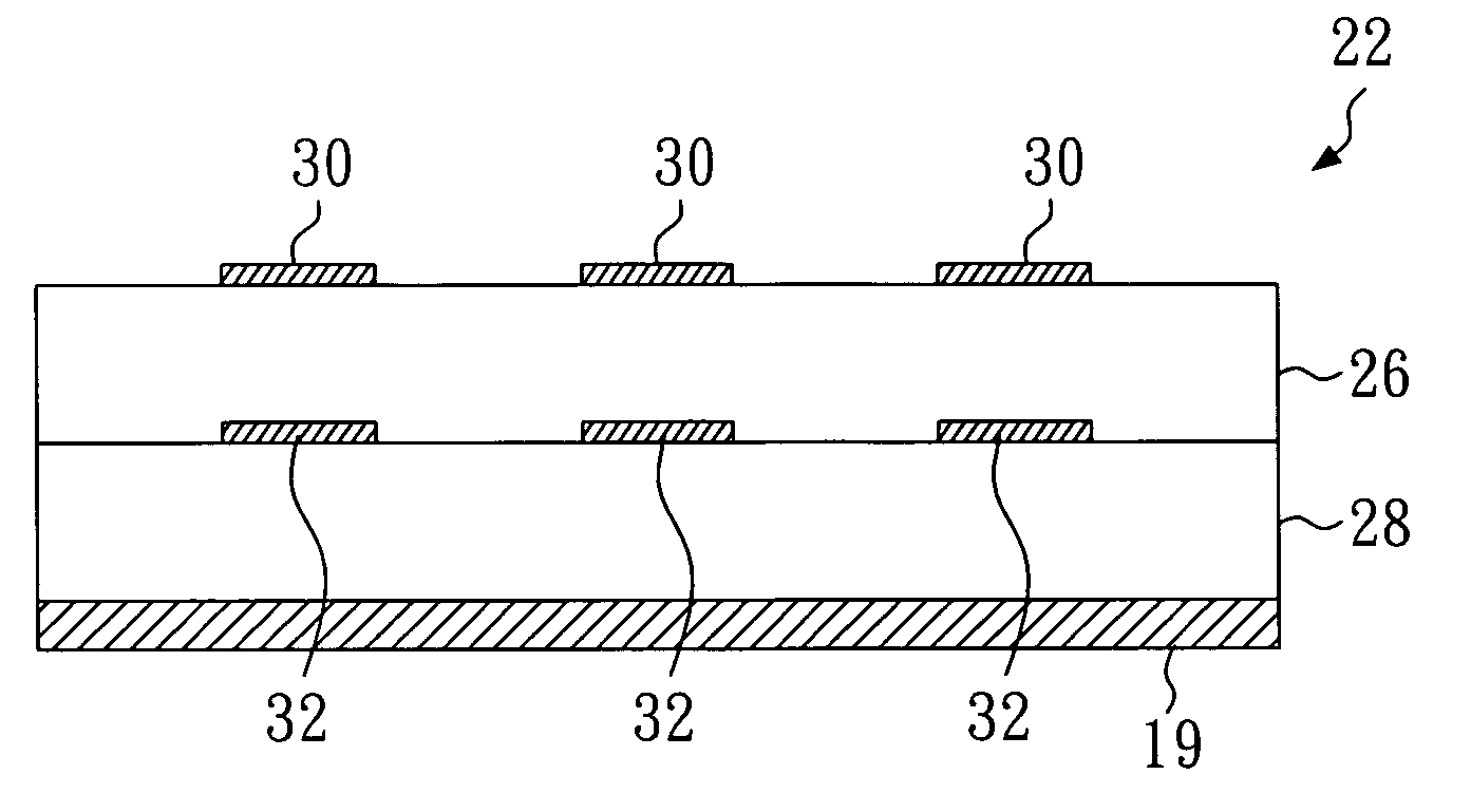
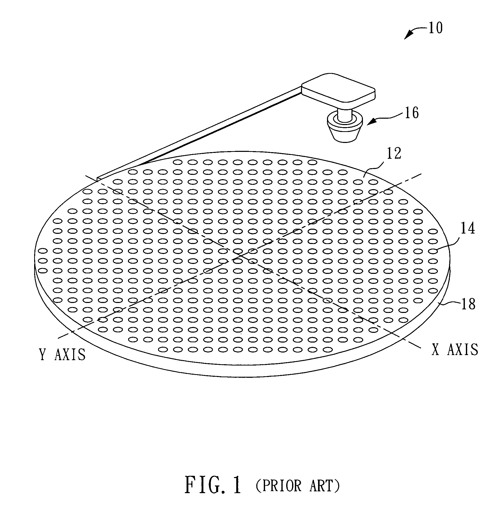
[0015]A microstrip reflective array antenna of the present invention and the traditional reflective array antenna are similar in structure, but differences exist in that the array unit of the microstrip reflective array antenna of the present invention uses U-slot patches and further uses the delay line of the U-slot patches to adjust the phase of microwave signal reflected by the array unit. Thus, its structure is still different from that of the array unit of the traditional reflect array antenna 10. As shown in FIG. 4, the microstrip reflective array antenna 20 of the present invention compromises the following elements:

[0016]A reflective disk 22, preferably a square disk, but which can also be traditional circular, hexagonal, octagonal, or similarly shaped disks, is provided for reflecting microwave signals from a far end and centralizing and reflecting the microwave signals to a horn antenna 16, or reflecting microwave signals reflected from the horn antenna 16 to the far end.

[...


PUM


Abstract

The present invention relates to a microstrip reflective array antenna adopting a plurality of U-slot patches. The microstrip reflective array antenna comprises a reflective disk, a horn antenna and a support. The reflective disk is adapted to reflect microwave signals wherein a plurality of square patches are disposed on the upper surface of a first substrate and a plurality of U-slot patches corresponding to the square patches are disposed on the upper surface of a second substrate. In addition, the lower surface of the first substrate is stacked on the upper surface of a second substrate. The horn antenna is adapted to receive the microwave signals from the reflective disk, and the support is adapted to hold the horn antenna directly above the reflective disk.

Description

BACKGROUND OF THE INVENTION[0001]1. Field of the Invention[0002]The present invention relates to a microstrip reflective array antenna and, more particularly, to a microstrip reflective array antenna adopting a plurality of U-slot patches.[0003]2. Description of Related Art[0004]The reflective array antenna has the advantages of being both easy to manufacture and having centralization of reflected microwave signals, thus it is popularly used to receive and transmit microwave signals. As shown in FIG. 1, the U.S. Pat. No. 6,195,047 / B1, entitled “Integrated microelectromechanical phase shifting reflective array antenna”, discloses a traditional reflective array antenna 10, comprising a traditional circular disk 12 and a horn antenna 16. A plurality of array units 14 of the traditional circular disk 12 reflect microwave signals transmitted from far away, then centralize and reflect the microwave signals to the horn antenna 16, and finally the horn antenna 16 receives the microwave sign...

Claims


Application Information

Patent Timeline
Patent Type & Authority Patents(United States)
IPC IPC(8): H01Q1/38H01Q9/04H01Q15/14H01Q19/10H01Q21/00H01Q21/06
CPCH01Q9/0414H01Q21/065H01Q19/104
Inventor CHANG, THE-NANLIAU, YU-LIN
Owner TATUNG UNIVERSITY
Why Eureka
Try Eureka