Self regulating detector rail heater for computed tomography imaging systems

a detector rail heater and computed tomography technology, applied in tomography, applications, instruments, etc., can solve the problems of leakage current, image accuracy, and one particularly acute source of error in this regard

Active Publication Date: 2007-01-09
GE MEDICAL SYST GLOBAL TECH CO LLC
View PDF4 Cites 5 Cited by
  • Summary
  • Abstract
  • Description
  • Claims
  • Application Information

AI Technical Summary

Problems solved by technology

Unfortunately, this is not the case for several reasons.
One particularly acute source of error in this regard has to do with how detector elements are affected by ambient conditions during operation.
Even slight variations in the temperature of the detector rails can cause this misalignment.
Obviously, if the detector elements are slightly misaligned, the resulting image will also be inaccurate.
Specifically, the shunt resistance of a photo diode drops exponentially with temperature which results in leakage current and in general a decrease in the signal noise to ratio.
When array output varies as a function of element and array environment temperature, the quality of the resulting image is adversely affected.
To this end, it has been observed that temperature effects on array output sometimes result in image artifacts that adversely affect the diagnostic usefulness of the resulting images.
There are many sources of heat in CT systems that directly affect the temperature of the array.
Specifically, the x-ray tube used to generate the x-ray beam generates a large amount of heat in CT systems.
These high powered systems, while appreciably faster than their predecessors, have exacerbated the array heating problem and thus the associated image degradation.
Unfortunately, the array temperatures occurring in high power systems often exceed the temperature bound which renders the heating configurations ineffective in maintaining an isothermal condition.
More simply, when detector temperature exceeds a target expected temperature level during some portion of an acquisition, the heating configuration which is limited by the upper temperature range is effectively useless.

Method used


Image

  • Self regulating detector rail heater for computed tomography imaging systems
  • Self regulating detector rail heater for computed tomography imaging systems
  • Self regulating detector rail heater for computed tomography imaging systems

Examples


Embodiment Construction

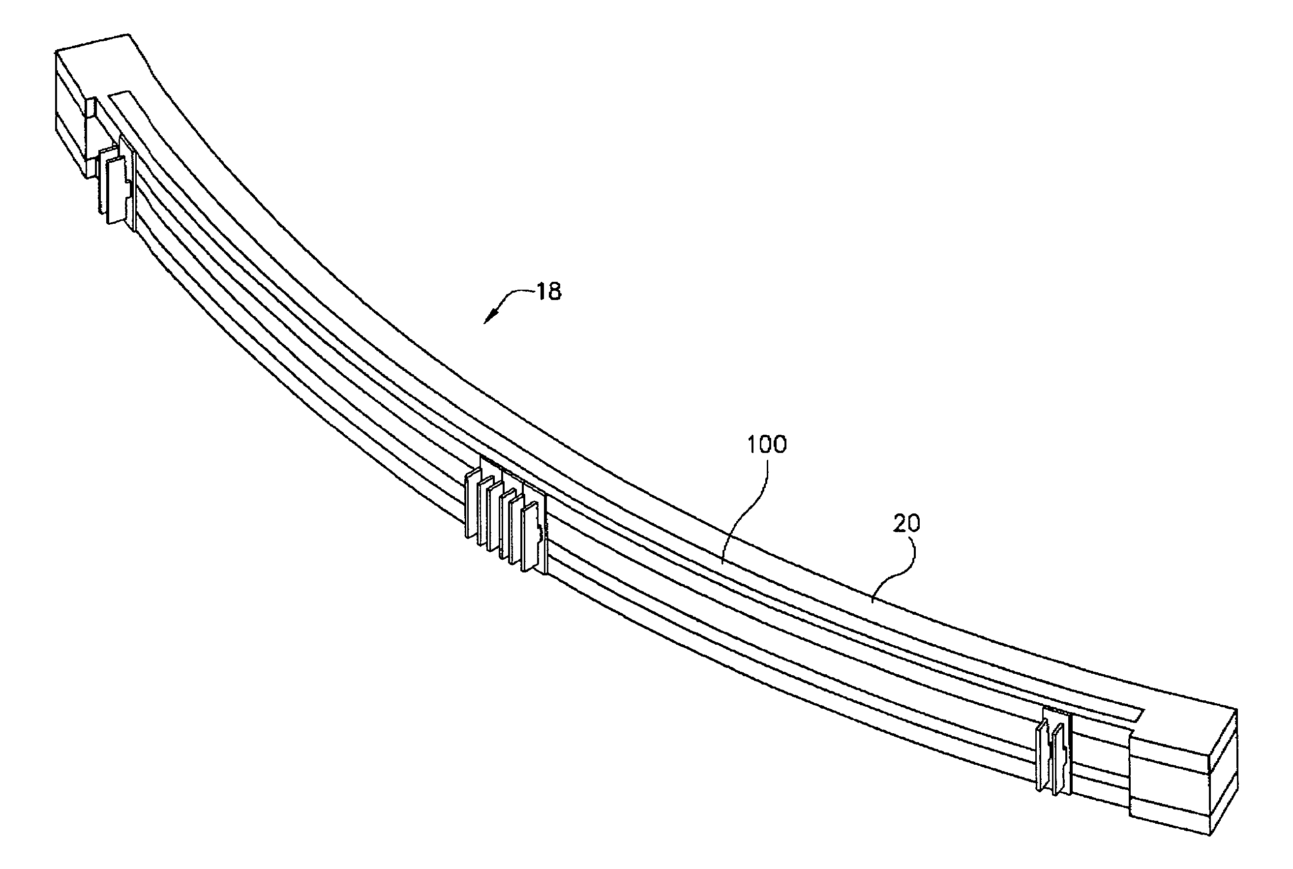
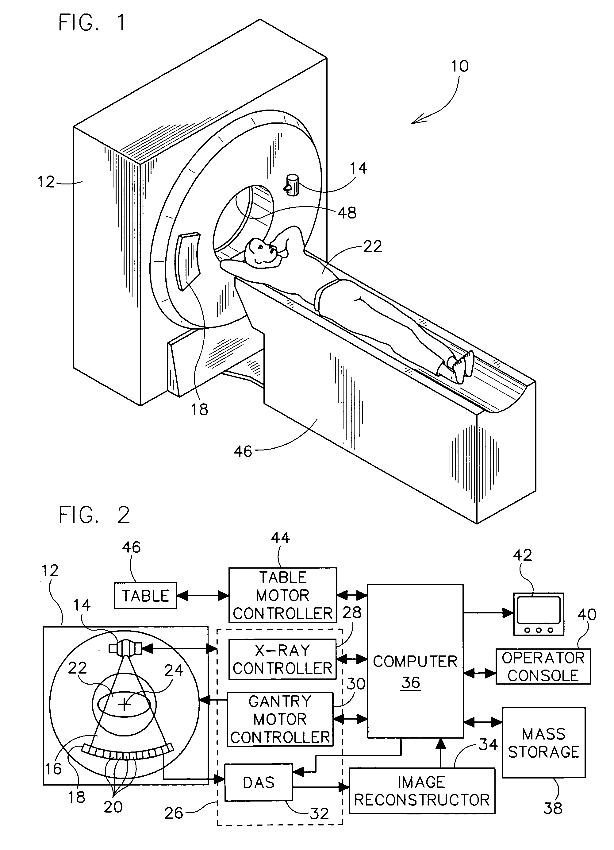
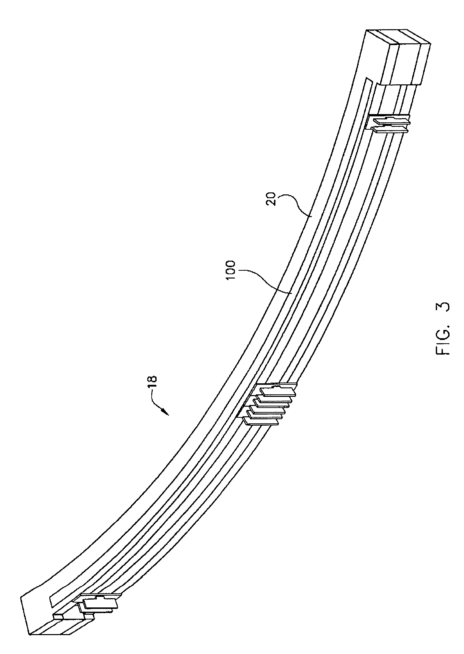
[0020]Referring now to the drawings in detail wherein like-numbered elements correspond to like elements throughout, FIGS. 1 and 2 show a multi-slice scanning computed tomography (CT) imaging system 10. The CT imaging system 10 is shown as including a gantry 12 representative of a “third generation” CT imaging system. Gantry 12 has an X-ray source 14 that projects a beam of X-rays 16 toward a detector array 18 on the opposite side of gantry 12. Detector array 18 is formed by a plurality of detector rows (not shown) including a plurality of detector elements 20 which together sense the projected X-rays that pass through an object, such as a medical patient 22. Each detector element 20 produces an electrical signal that represents the intensity of an impinging X-ray beam and hence the attenuation of the beam as it passes through object or patient 22. During a scan to acquire X-ray projection data, gantry 12 and the components mounted thereon rotate about a center of rotation 24. FIG. ...


PUM


Abstract

The present application discloses an x-ray detector for use in a computed tomography (CT) imaging system. The x-ray detector assembly comprises an array of detector cells coupled between detector rails. The present invention provides a self regulating heating element having a body that, when current is passed therethrough, radiates heat until a specific reference temperature is reached, at which point the resistance of the PTC heater increases, thus reducing the current through the PTC heater, and, as a result, the radiative heating of the PTC heater.

Description

BACKGROUND OF THE INVENTION[0001]The present invention relates generally to computed tomography (CT) imaging systems. More particularly, it relates to a method and apparatus for heating the detector rail of a CT imaging system.[0002]In at least some CT imaging system configurations, a stationary floor-mounted frame includes an x-ray source and a radiation detector array. The x-ray source projects a fan-shaped beam that is collimated to lie within an X-Y plane of a Cartesian coordinate system and is generally referred to as the “imaging plane”. The x-ray beam passes through the object being imaged, such as a patient. The beam, after being attenuated by the object, impinges upon the array of radiation detectors. The intensity of the attenuated beam radiation received at the detector array is dependent upon the attenuation of the x-ray beam of the object. Each detector element of the array produces a separate electrical signal that is a measurement of the beam attenuation at the detect...

Claims


Application Information

Patent Timeline
Patent Type & Authority Patents(United States)
IPC IPC(8): G01T1/24A61B6/03
CPCA61B6/54A61B6/4233
Inventor LACEY, JOE J.
Owner GE MEDICAL SYST GLOBAL TECH CO LLC
Why Eureka
Try Eureka