
High efficiency solar cells

Inactive Publication Date: 2007-01-09
GR INTELLECTUAL RESERVE LLC
View PDF10 Cites 0 Cited by
  • Summary
  • Abstract
  • Description
  • Claims
  • Application Information

AI Technical Summary

Benefits of technology

[0009]Another object of the invention is to limit or restrict certain undesirable incident wavelengths of light (and thus certain frequencies and energy levels) from becoming incident upon a solar cell photovoltaic substrate.
[0011]It is an object of the invention to determine which particular energies (and thus which particular wavelengths or frequencies) of incident light are required for any desired solar cell photovoltaic substrate to permit desirable interactions to occur (e.g., for electrons to be excited from one energy level to another to result in current; to provide energy to the electrons which can assist in promoting the electrons to a conduction band to result in current; and after determining which energies (and thus which wavelengths or frequencies) are desirable, substantially restricting the wavelengths or frequencies of undesirable incident light upon said substrate by utilizing an appropriate filtering technique or light modifying (e.g., shifting, refracting, etc.) technique, thus maximizing those desirable energies of light which contact or are incident upon a solar cell substrate.
[0014]It is an object of the invention to provide a glass cover material which is capable of filtering, refracting and / or reflecting out as many undesirable wavelengths of incident light as possible and thus maximizing the incidences of those wavelengths of light which desirably interact with a solar cell photovoltaic substrate material after passing through such a cover material.
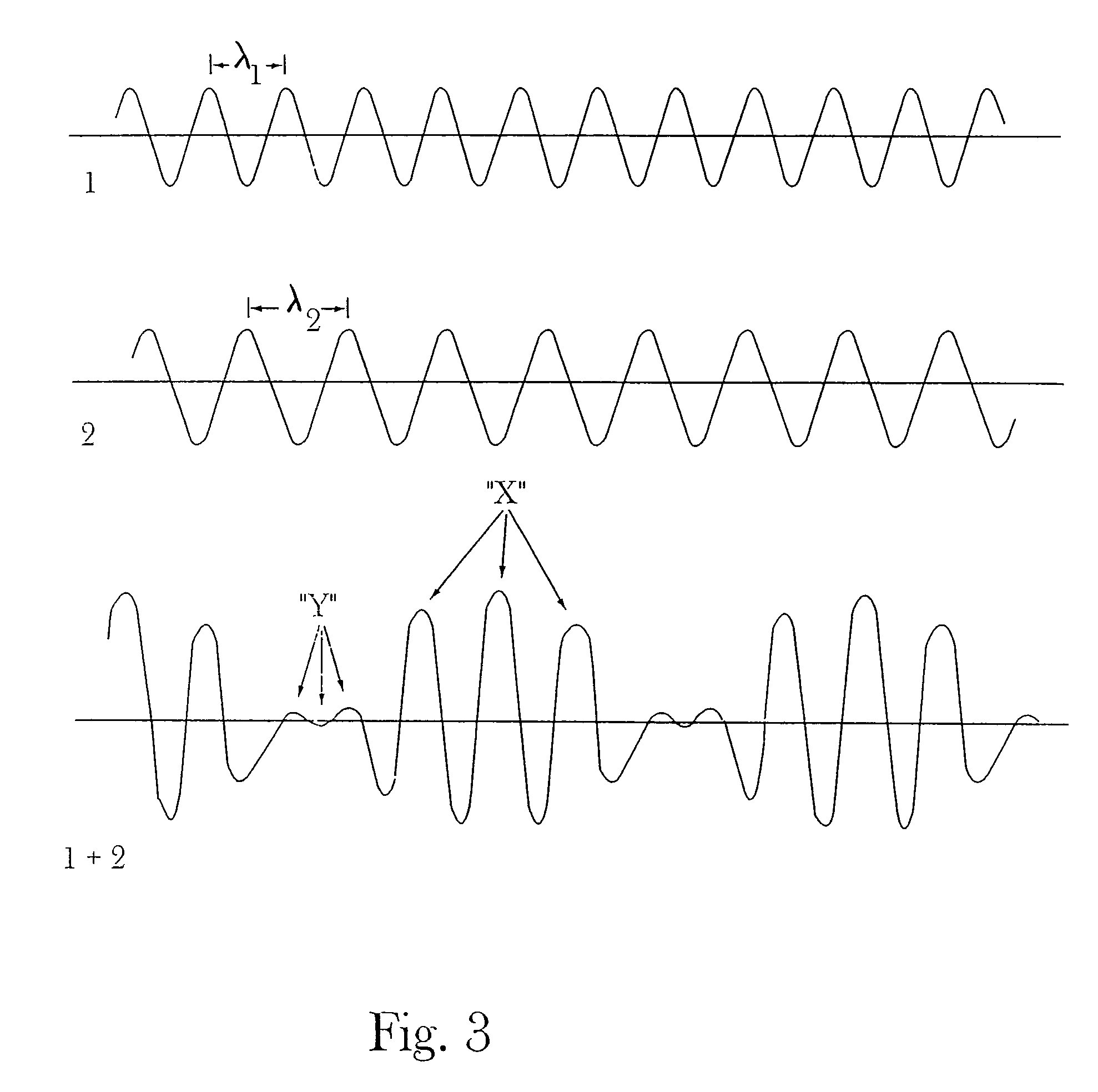
[0025]Accordingly, the present invention satisfies the long felt need in the solar cell industry to render solar cells more efficient by recognizing that it is not desirable for all wavelengths of light within any particular spectrum of light (e.g., natural sunlight) to be incident upon a solar cell photovoltaic substrate (e.g., crystalline silicon, amorphous silicon, single crystal silicon, cadmium sulfide, etc.) but rather to reduce or limit the incident light to as many of those wavelengths as possible which can result in predominantly desirable interactions between the incident light and the solar cell's photovoltaic substrate (i.e., in other words, to reduce as many negative or destructively interfering wavelengths of light as possible so as to reduce negative effects of, for example, destructive interference occurring in the photovoltaic substrate).
[0029]Still further, in some instances certain blocks or regions of incident light may be desirable to prevent from contacting a photovoltaic material. In this regard it may be desirable to block out complete portions of infrared wavelengths and / or complete portions of ultraviolet wavelengths to improve performance.

Problems solved by technology

For example, it is relatively expensive to manufacture those semiconductor materials currently utilized for solar cells (e.g., crystalline silicon, amorphous silicon, cadmium sulfide, etc.) into solar panels (e.g., typically, a plurality of combined solar cells electrically connected together) which includes the high costs of forming the solar cell substrate materials themselves, the cost of modifying the substrate materials so that they can become photovoltaic (e.g., doping the semiconductor substrate material to create substrate p / n junctions, etc.), the placement of electron collecting grids on surfaces of the solar cells, manufacturing the solar cells into solar panels, etc.
However, this entire process has historically been relatively inefficient, making the solar cell industry less than ideal.

Method used


Image

  • High efficiency solar cells
  • High efficiency solar cells
  • High efficiency solar cells

Examples


Embodiment Construction

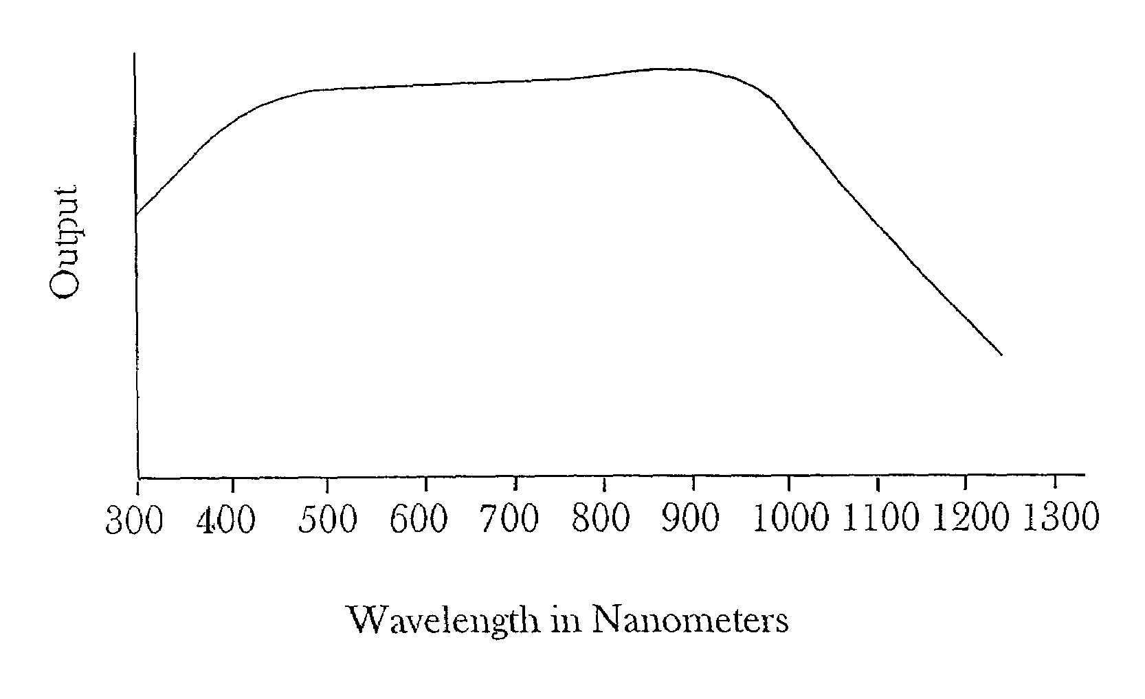
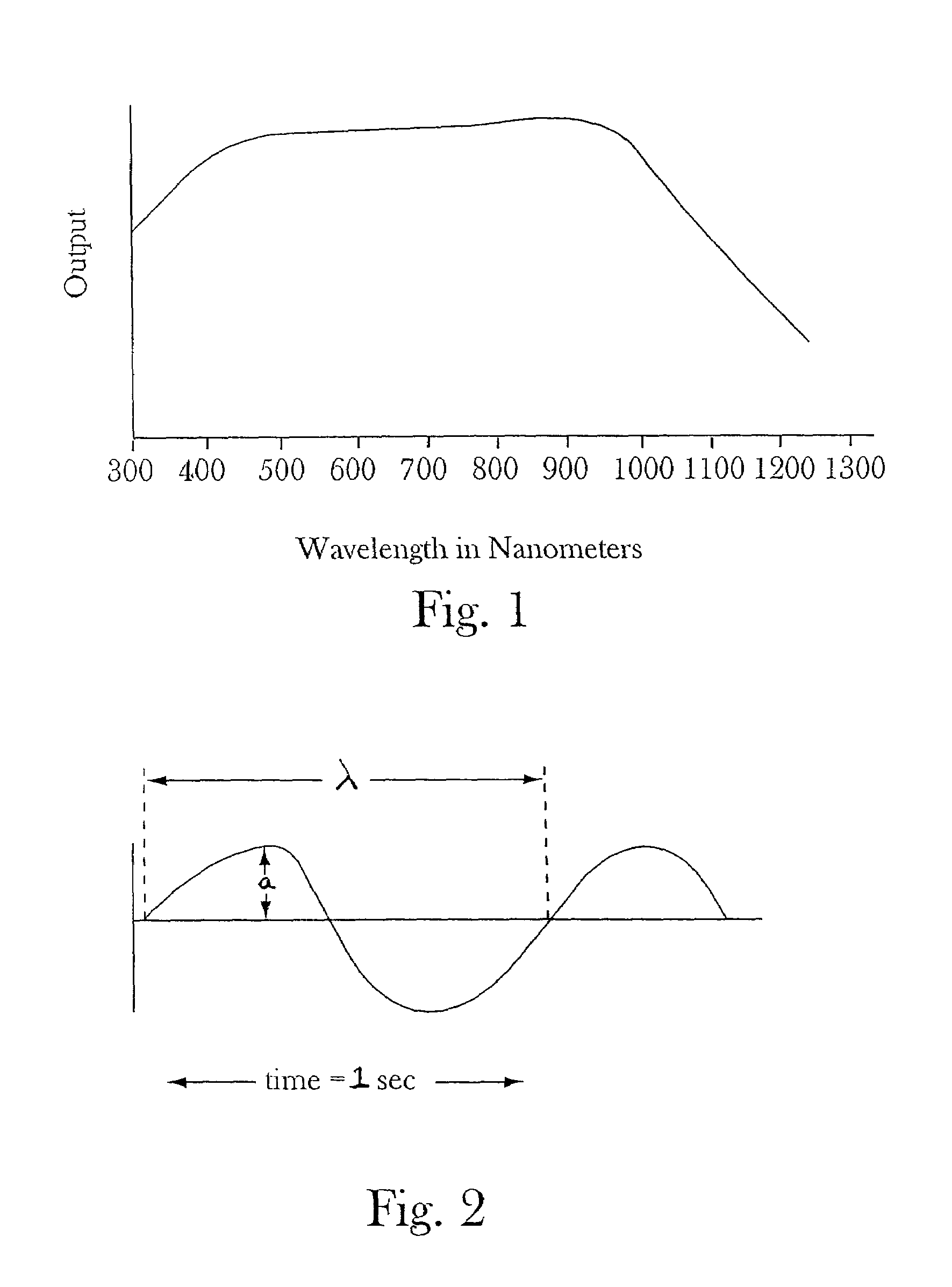
[0037]FIG. 1 shows a typical output response for a crystalline silicon solar cell. In this regard, the x-axis corresponds to wavelengths from about 300 nanometers to about 1400 nanometers, which is the typically desired response range that traditional solar cell manufacturers have sought for the photovoltaic material(s) comprising the solar cell. The y-axis corresponds to a particular output present at various measured wavelengths along the x-axis. The prior art is replete with attempts to describe means for utilizing more and more of the wavelengths contained in sunlight (e.g., light trapping techniques, etc.), however, the prior art misses the point that undesirable effects can also occur at the same time that certain desirable effects are occurring resulting in a canceling or blocking out of some of the desirable effects.

[0038]In this regard, for example, FIG. 2 shows a first sine wave which corresponds to a particular wavelength “λ”, a certain amplitude “a” and a frequency of 1 ...


PUM


Abstract

The present invention relates to improvements in solar cell and solar panel photovoltaic materials which cause the solar cells / panels to operate more efficiently. In particular, the present invention focuses primarily on matching or modifying particular incident light energies (e.g., from the sun) to predetermined energy levels in a solar cell photovoltaic substrate material required to excite, for example, electrons in at least a portion of the substrate material in a desirable manner. In this regard, for example, energy levels of incident light, and thus, corresponding particular wavelengths, such as desirable wavelength (γ1), or frequenices of incidient light, can be at least partially matched with various desirable energy levels in a substrate material by filtering out at least a portion of certain undesirable incident light, such as that of wavelength (γ2), that comes into contact with at least a portion of a surface of a solar cell photovlataic substrate.

Description

[0001]This application is a 371 of PCT / US02 / 15549, filed May 16, 2002, which claims benefit of provisional application 60 / 291,357, filed May 16, 2001.FIELD OF THE INVENTION[0002]The present invention relates to improvements in solar cell and solar panel photovoltaic materials which cause the solar cells / panels to operate more efficiently. In particular, the present invention focuses primarily on matching or modifying particular incident light energies (e.g., from the sun) to predetermined energy levels in a solar cell photovoltaic substrate material (e.g., a semiconductor material) required to excite, for example, electrons in at least a portion of the substrate material in a desirable manner (e.g., to cause desirable movement of electrons to result in output amperages previously unobtainable). In this regard, for example, energy levels of incident light, and thus, corresponding particular wavelengths or frequencies of incident light, can be at least partially matched with various d...

Claims


Application Information

Patent Timeline
IPC IPC(8): H01L31/00H01L31/0232H01L31/0216H01L31/04H01L31/052H01L31/054
CPCH01L31/02164H01L31/02167H01L31/0547H01L31/0543Y02E10/52
Inventor MORTENSON, MARK G.
Owner GR INTELLECTUAL RESERVE LLC
Learn More