Motorized hammock swinging assembly

a motorized, hammock technology, applied in the field of assembly, can solve the problems of not being comfortable, requiring physical exertion by the user, and devices relatively expensive to manufacture and maintain, and achieve the effect of satisfying the experience of using the device, being easy to manufacture, acquire and maintain, and being easy to us

Inactive Publication Date: 2007-01-09
VOORTING ARIC R
View PDF57 Cites 13 Cited by
  • Summary
  • Abstract
  • Description
  • Claims
  • Application Information

AI Technical Summary

Benefits of technology

[0008]The motorized hammock swinging assembly of the present invention addresses the aforementioned needs in the art. The motorized hammock swinging assembly is an automated hammock swinging system that is relatively simple in design and construction, so that the assembly is relatively inexpensive to manufacture, acquire, and maintain. The motorized hammock swinging assembly provides a swinging motion that is very smooth and fluid and not static and jerky, so that the user of the present invention has a very satisfying experience using the device. The motorized hammock swinging assembly allows the user to vary the speed of swing in order to achieve the optimal speed level for the user. The motorized hammock swinging assembly is simple to assemble, install, and operate and is portable.

Problems solved by technology

While this method does result in hammock swinging, it requires the user to exert energy, which draws away somewhat from the relaxation process and also requires the user to have one foot dangling, which is not as comfortable as lying fully within the hammock bed.
While this situation is ideal to the hammock user, the person swinging the hammock, who may not be available in the first place, will soon tire of the undertaking and will go off to other tasks leaving the hammock user with the need to find alternate ways to swing the hammock.
However, this method also requires physical exertion by the user and also proves ineffective when using a low-rise hammock support structure.
However, the prior art devices tend to be relatively complex in design and construction making such devices relatively expensive to manufacture and maintain.
Other prior art devices, while automatically swinging the hammock, cause the swinging to be somewhat jerky and not smooth and continuous, the result being a less than completely satisfying experience.
Still other devices swing the hammock at a speed that is too fast for the desires of the user, again taking away from the hammock experience.

Method used


Image

  • Motorized hammock swinging assembly
  • Motorized hammock swinging assembly
  • Motorized hammock swinging assembly

Examples


Embodiment Construction

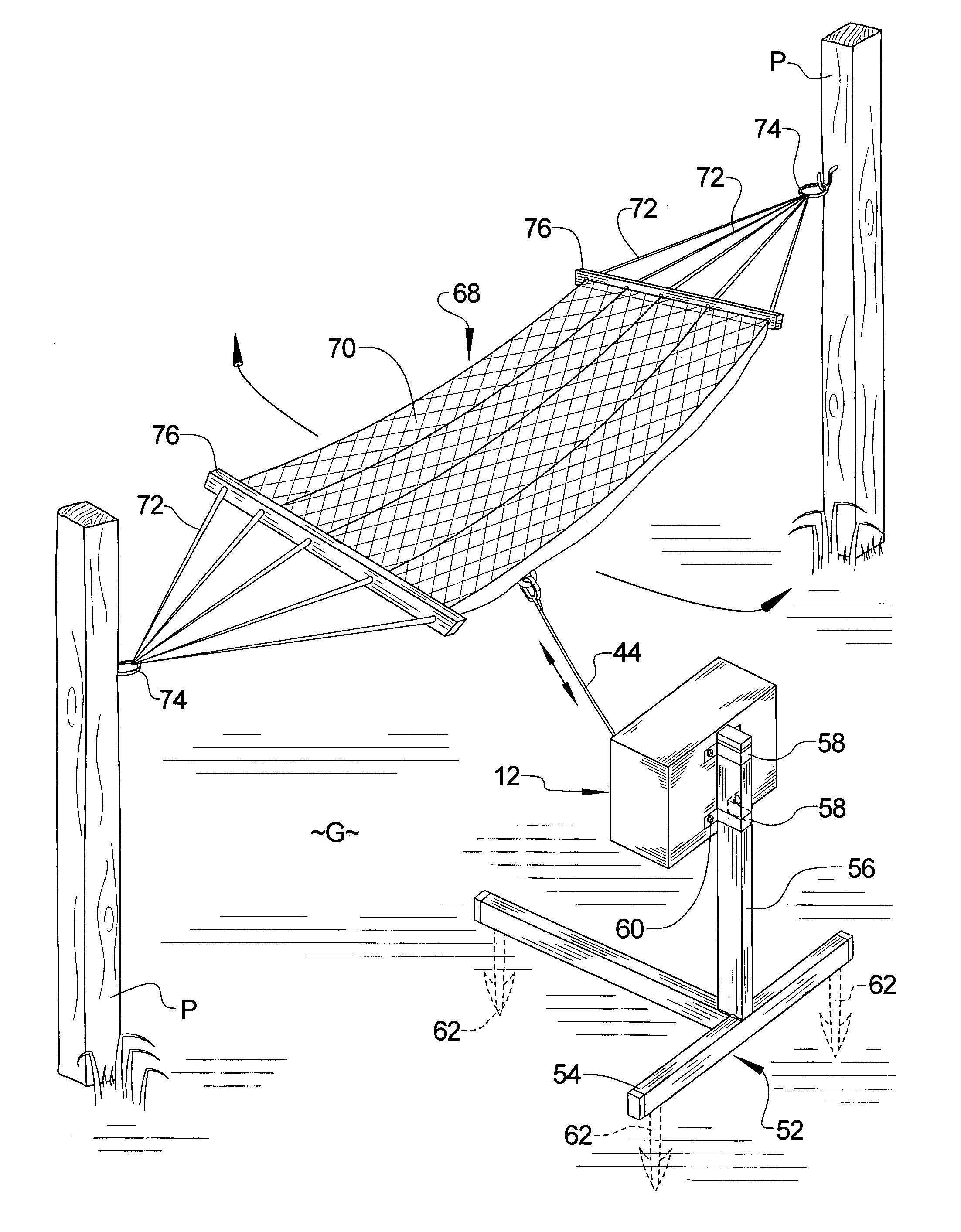
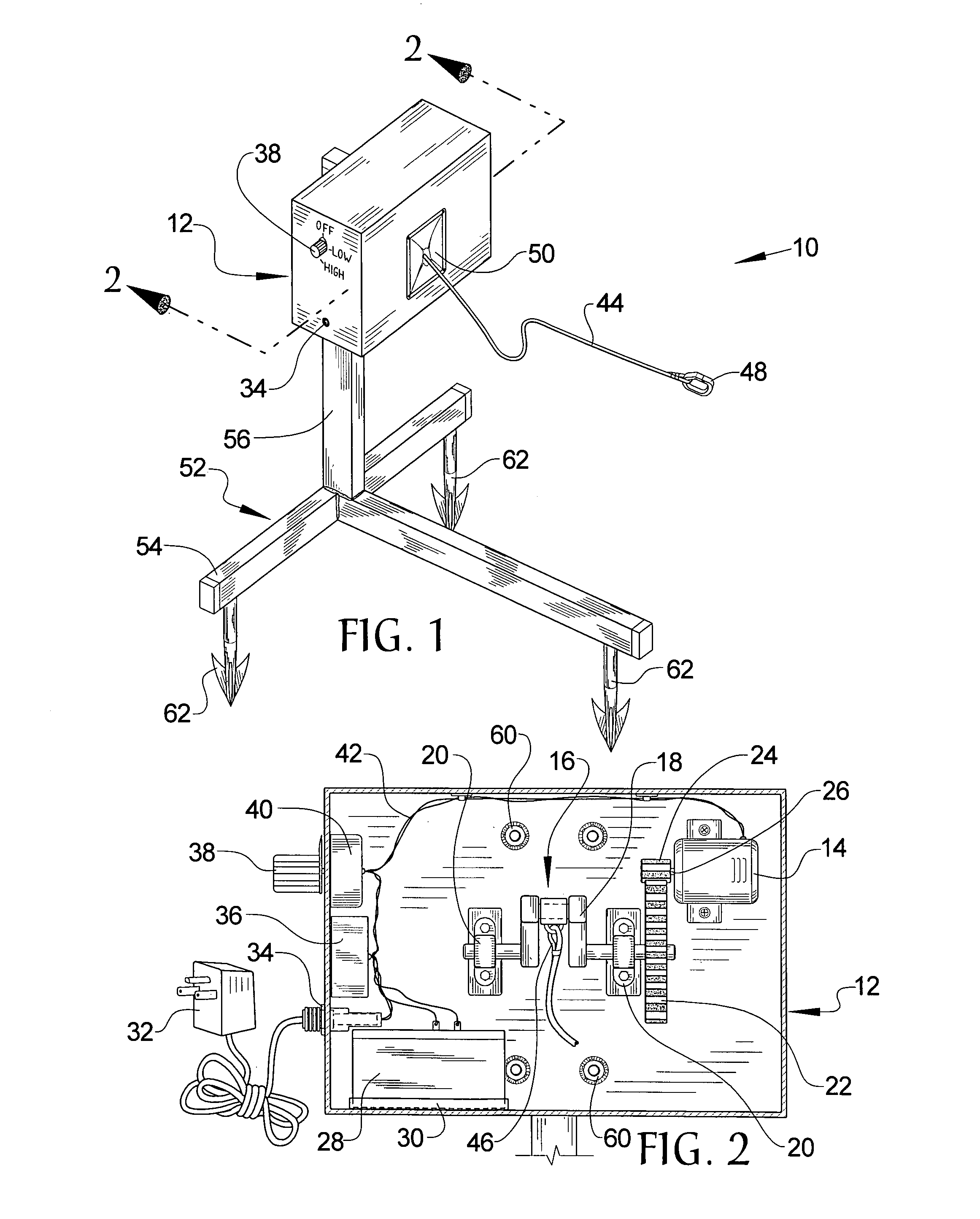
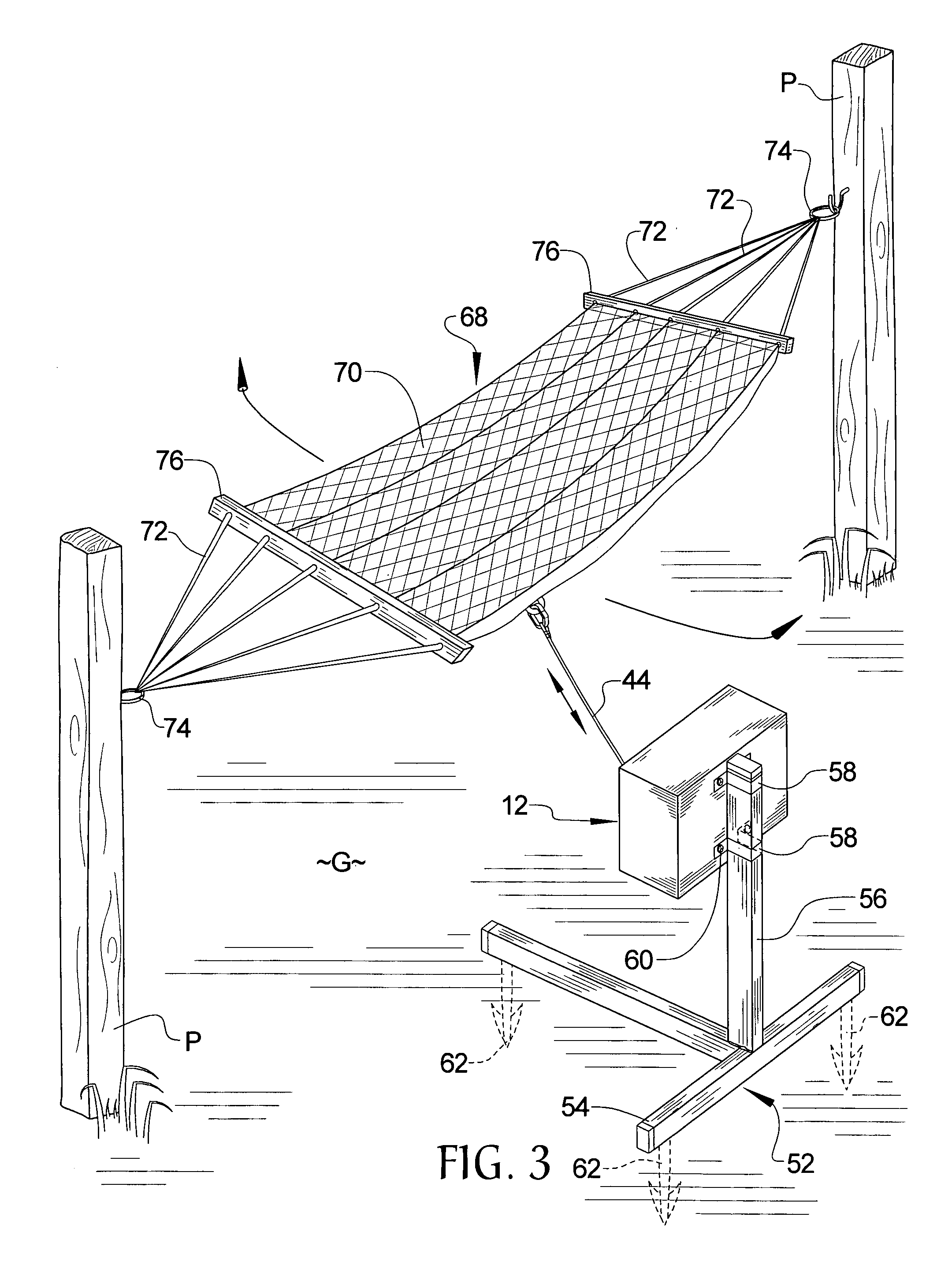
[0016]Referring now to the drawings, it is seen that the motorized hammock swinging assembly, generally denoted by reference numeral 10, is comprised of a housing 12 having a motor 14 located therein. A crank assembly 16 is located within the housing 12 and is operatively connected with the motor 14. The crank assembly 16 includes a crankshaft 18 that has either end anchored within a crank bearing 20. A crank gear 22 is attached to one end of the crankshaft 18 and meshes with a drive gear 24 attached on the end of the drive shaft 26 of the motor 14. Whenever the motor 14 is operational, its drive shaft 26 rotates, which causes the drive gear 24 on the end of the drive shaft 26 to rotate. The rotating drive gear 24, being meshed with the crank gear 22, causes the crank gear 22 to rotate, which in turn causes the crankshaft 18 to rotate. The motor 14 is powered by either a battery 28 located on a battery tray 30 within the housing or by a source of standard household power such that a...


PUM


Abstract

A motorized hammock swinging assembly automatically swings a hammock back and forth. A housing has a motor operationally connected with a crankshaft assembly. A cable is attached to a crankshaft of the crankshaft assembly and to the hammock such that when the motor is operation, the crankshaft rotates causing the cable to be pulled back and forth. The reciprocating cable causes the hammock to be swayed back and forth. The housing can be frame mounted such that the frame is secured to the ground at its point of operation, or the housing can be mounted to a structure such as a tree. The motor can be run by a battery located within the housing or by a source of AC electrical power, which source can be used to charge the battery or by a solar cell.

Description

BACKGROUND OF THE INVENTION[0001]1. Field of the Invention[0002]The present invention relates to an assembly used with a suspended hammock which assembly has a motorized swinging mechanism associated for imparting on the hammock in order to swing the hammock.[0003]2. Background of the Prior Art[0004]Nothing beats lying in a hammock with little to do but relax and maybe read a good book. Gently swaying in the breeze with the trees blocking the direct shine of the sun, a cool drink nearby, and the gentle sounds of nature is the good life indeed. What could be a more relaxing way to spend a quiet weekend afternoon. Due to the comfort and tranquillity of modern hammocks, such devices have become increasingly popular over the years. With the advent of portable hammocks and hammock frames, hammocks are no longer limited to areas where to solid trees are located an appropriate distance apart from one another, they are found almost anywhere where tranquillity beckons.[0005]One undertaking t...

Claims


Application Information

Patent Timeline
Patent Type & Authority Patents(United States)
IPC IPC(8): A45F3/22
CPCA45F3/22
Inventor VOORTING, ARIC R.
Owner VOORTING ARIC R
Why Eureka
Try Eureka