Patio umbrella support apparatus

Inactive Publication Date: 2007-01-02
KOCUR WILLIAM M
View PDF9 Cites 20 Cited by
  • Summary
  • Abstract
  • Description
  • Claims
  • Application Information

AI Technical Summary

Benefits of technology

[0007]It is another object of this invention to provide stable support for a patio umbrella substantially irrespective of where the patio umbrella is to be placed on the patio deck.
[0009]It is an advantage of this invention that the umbrella stand can be moved to permit the movement of a patio table having an umbrella to a desired selected position on the deck.
[0020]It is a further advantage of this invention that the upper flange provides positional stability for the umbrella support apparatus on the top surface of the deck, while the anchoring fin limits movement of the apparatus across the surface of the deck, as limited by deck support beams below the deck planking.
[0021]It is yet another object of this invention to provide a patio umbrella support apparatus, which is durable in construction, inexpensive of manufacture, carefree of maintenance, facile in assemblage, and simple and effective in use.
[0022]These and other objects, features and advantages are accomplished according to the instant invention by providing a patio umbrella support apparatus that is operable to be engaged by the mast of a patio umbrella to permit the positioning of the patio umbrella at desired, selected positions on a patio deck built with deck planks spaced apart by a conventional gap. The umbrella support apparatus is formed with an upright support member affixed to a pair of opposing horizontal support flanges that ride on top of the deck surface. A generally vertical anchoring fin is affixed to the support flanges and upright support member to fit within the conventional gap between deck planks. The anchoring fin and the horizontal flanges provide positional stability for the patio umbrella and permit flexibility in the location of the umbrella on the deck. A notch formed in the anchoring fin can receive a deck support cross beam and further limit movement of the umbrella support apparatus relative to the deck.

Problems solved by technology

While movement of the Galloway umbrella stand does not require access to a clamping apparatus beneath the patio decking, location of the support devices is limited to proximity to an elevated support member, such as a deck railing or the like.
Furthermore, the Galloway support apparatus is hampered by the lack of restraint to the movement of the bottom stand member that receives the base of the patio umbrella.

Method used


Image

  • Patio umbrella support apparatus
  • Patio umbrella support apparatus
  • Patio umbrella support apparatus

Examples


Embodiment Construction

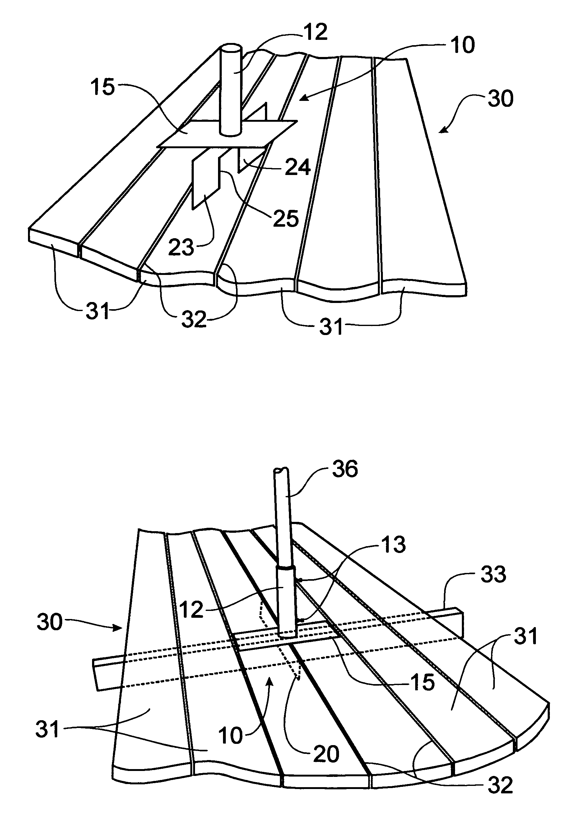
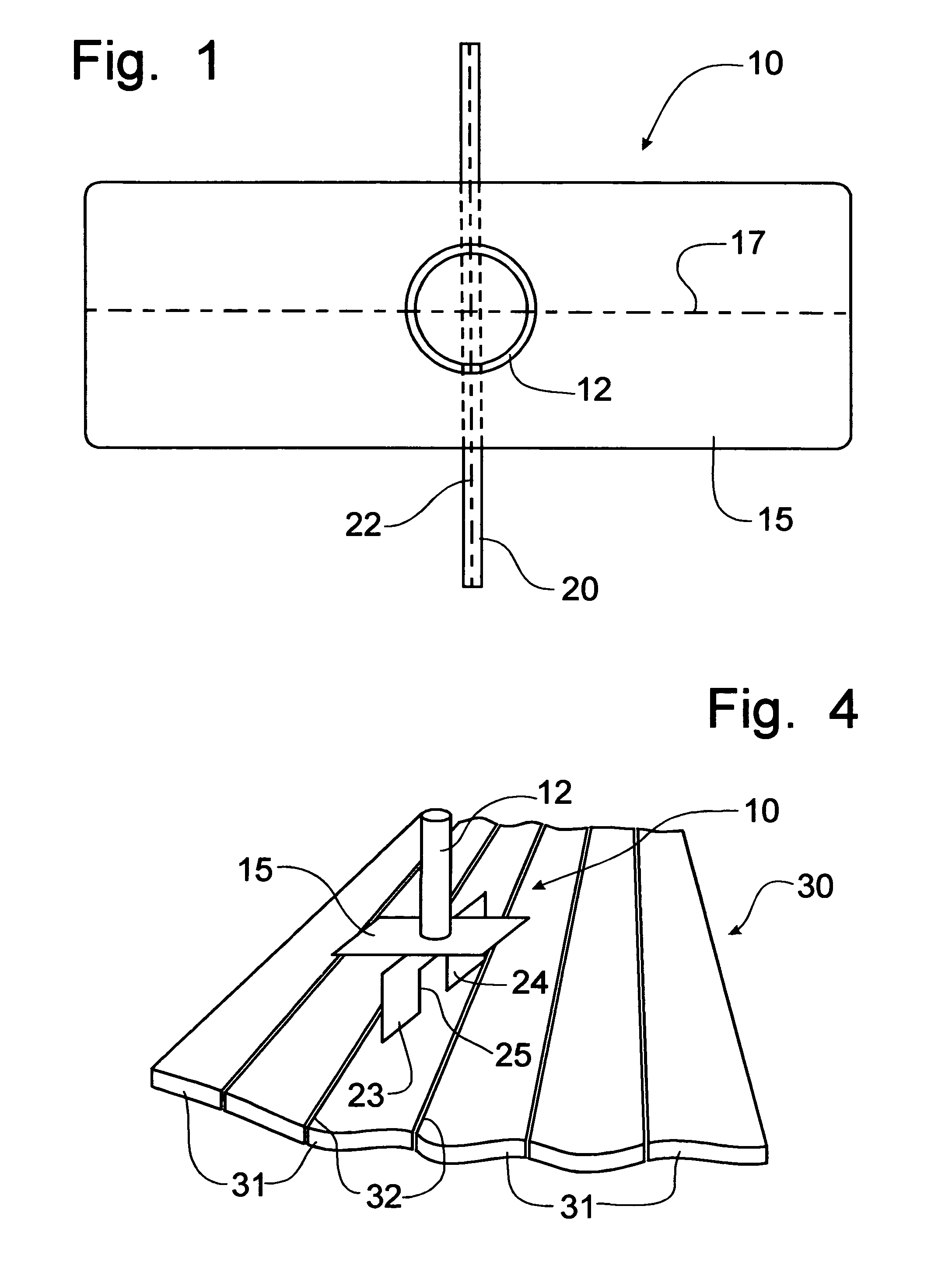
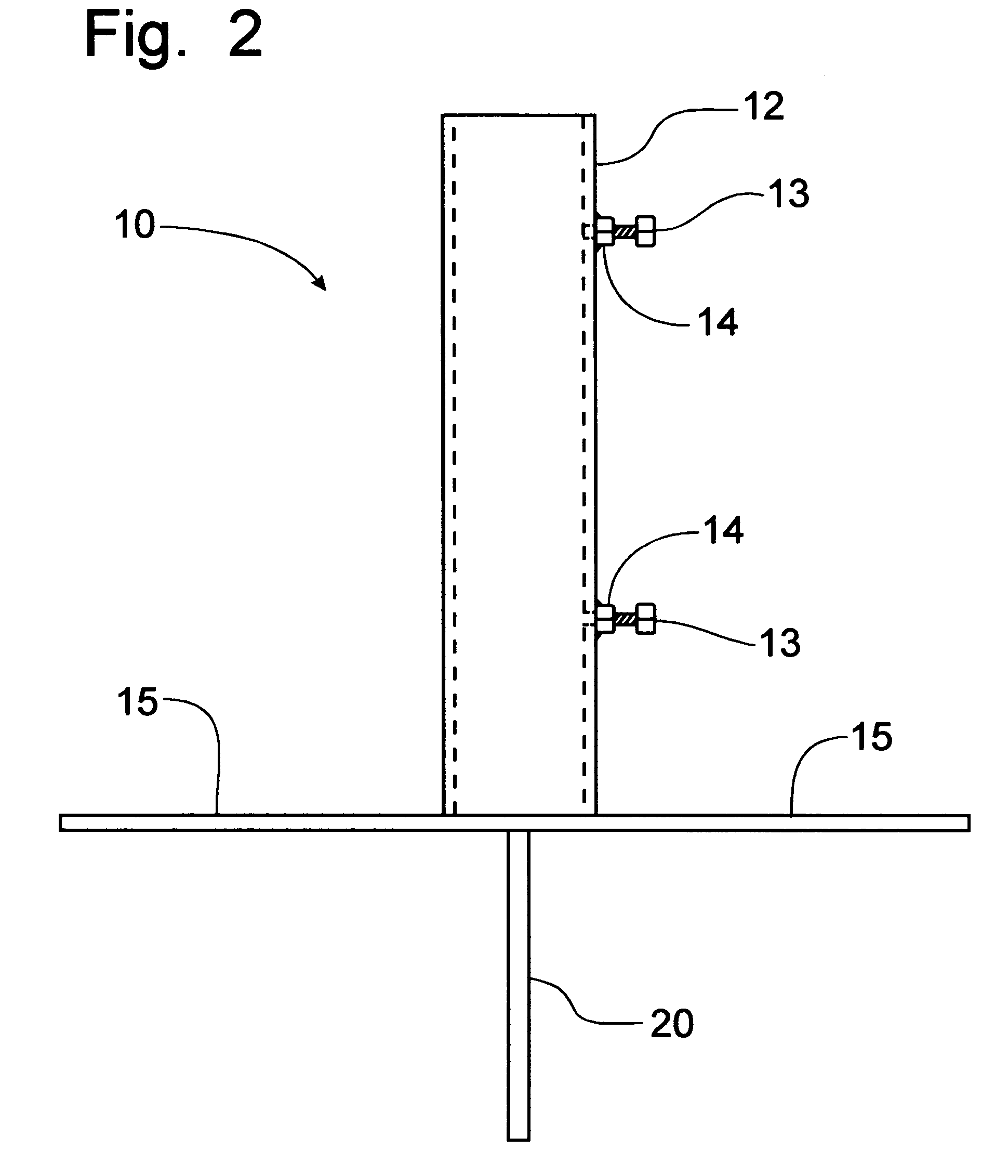
[0032]Referring now to FIGS. 1–7, a patio umbrella stand for use to support a patio umbrella 35 associated with a patio table 38 in conjunction with a patio deck 30 formed with flooring planks 31 can best be seen. As best seen in FIGS. 1–3, the patio umbrella stand 10 is formed from an upright tubular member 12 having an open top sized to receive the base of a patio umbrella mast 36. The upright tubular member 12 is preferably formed of steel pipe having a diameter of approximately one and three-quarters inches and is welded to a horizontally disposed, rectangular flange member 15 to project the upright tubular member 12 perpendicularly thereto. Below the rectangular flange 15, a vertical anchoring fin 20 is welded to the bottom of the rectangular flange 15 in a manner to position the axis 22 thereof perpendicular to the major axis 17 of the rectangular flange 15. The anchoring fin 20 is preferably formed with downwardly depending, opposing lobes 23, 24 with a notch 25 formed thereb...


PUM


Abstract

A patio umbrella support apparatus can be engaged by the mast of a patio umbrella to permit the positioning of the patio umbrella at desired, selected positions on a patio deck built with deck planks spaced apart by a conventional gap. The umbrella support apparatus is formed with an upright support member affixed to a pair of opposing horizontal support flanges that ride on top of the deck surface. A generally vertical anchoring fin is affixed to the support flanges and upright support member to fit within the conventional gap between deck planks. The anchoring fin and the horizontal flanges provide positional stability for the patio umbrella and permit flexibility in the location of the umbrella on the deck. A notch formed in the anchoring fin can receive a deck support cross beam and further limit movement of the umbrella support apparatus relative to the deck.

Description

CROSS-REFERENCE TO RELATED APPLICATIONS[0001]This application claims domestic priority on U.S. Provisional Patent Application Ser. No. 60 / 488,114, filed on Jul. 17, 2003, the contents of which are incorporated herein by reference.BACKGROUND OF THE INVENTION[0002]The present invention relates generally to a device for holding an umbrella, such as a patio umbrella, on a deck formed from planking, and, more particularly, to a support apparatus that receives a patio umbrella mast for selective positioning the umbrella on a patio deck.[0003]Patio furniture, such as a patio table, can be formed with an opening extending vertically therethrough for the passage of a patio umbrella. In some patio tables, the frame for the support of the patio table includes an integral holder for the base of the patio umbrella. In other configurations, such as is depicted in U.S. Pat. No. 5,685,517, issued to Joseph Salibra on Nov. 11, 1997, the stand for mounting the base of the patio umbrella is bolted or ...

Claims


Application Information

Patent Timeline
IPC IPC(8): F16M13/00
CPCE04H12/2269E04H12/2215
Inventor KOCUR, WILLIAM M.
Owner KOCUR WILLIAM M
Why Eureka
Try Eureka