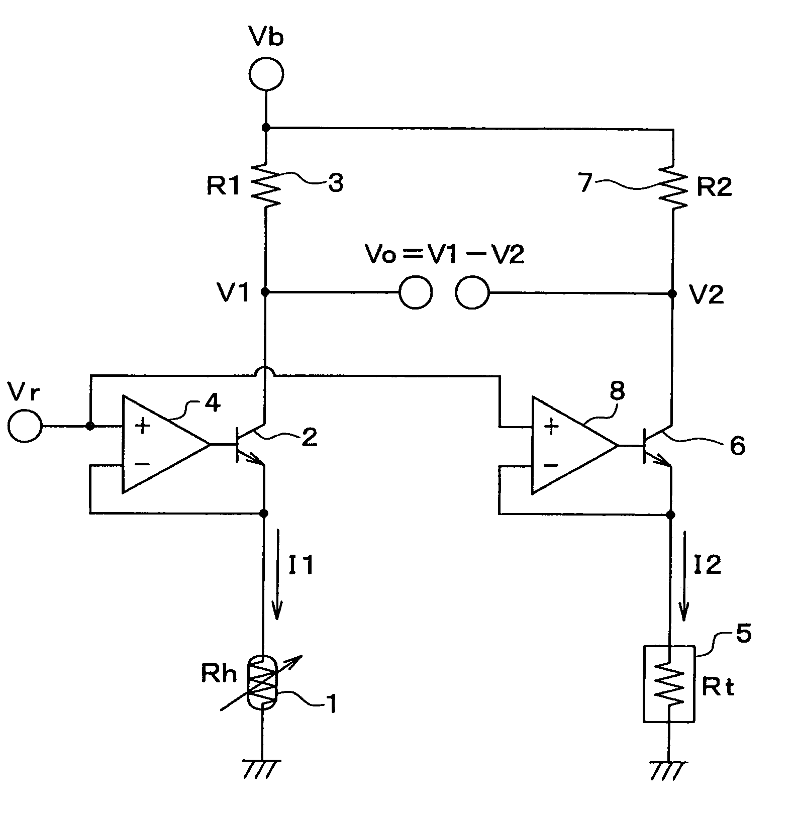
Heat-radiation type flow sensor
a flow sensor and heat radiation technology, applied in the direction of volume/mass flow measurement, measurement devices, instruments, etc., can solve the problems of circuit system oscillation, emi filter add costs, circuit system is not well able to endure electromagnetic interference, etc., to achieve strong endurance and well withstanding electromagnetic interference
- Summary
- Abstract
- Description
- Claims
- Application Information
AI Technical Summary
Benefits of technology
Problems solved by technology
Method used
Image
Examples
first embodiment
(First Embodiment)
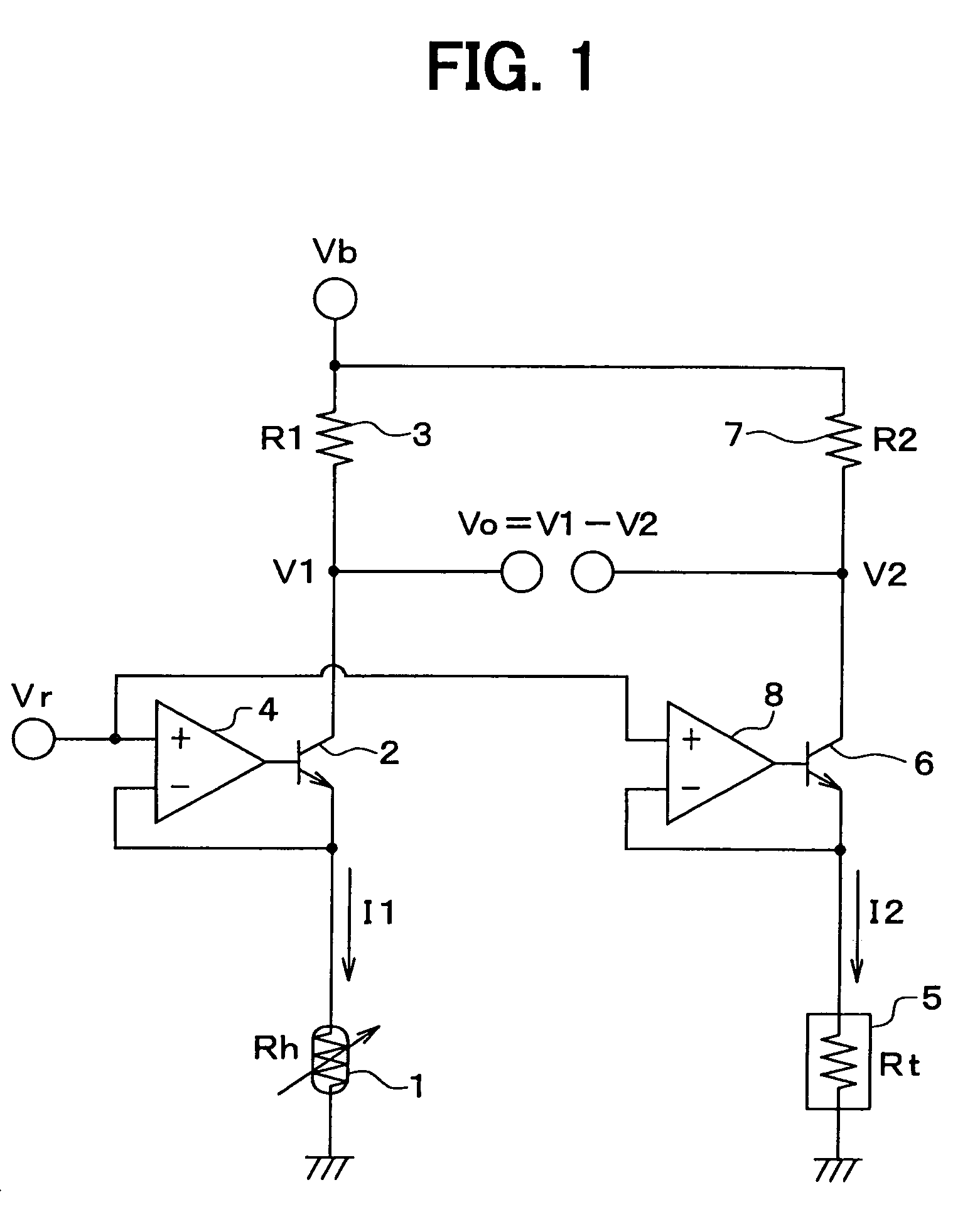
[0020]Referring to FIG. 1, an airflow sensor comprises a heater resistor 1, an NPN transistor 2, a resistor 3 and an operational amplifier 4. The heater resistor 1 is connected to the emitter of the NPN transistor 2 and the resistor 3 is connected to the collector of the NPN transistor 2 to form a series circuit including the heater resistor 1, the NPN transistor 2 and the resistor 3 along a first current path. A power supply Vb supplies a current to the first current path.
[0021]An electrical potential appearing at a junction between the heater resistor 1 and the emitter of the NPN transistor 2 is supplied to an inverting input terminal of the operational amplifier 4. On the other hand, a constant voltage Vr is supplied to a non-inverting input terminal of the operational amplifier 4. An electrical potential appearing at the output terminal of the operational amplifier 4 is supplied to the base of the NPN transistor 2 as a base voltage to adjust the magnitude of a ...
second embodiment
(Second Embodiment)
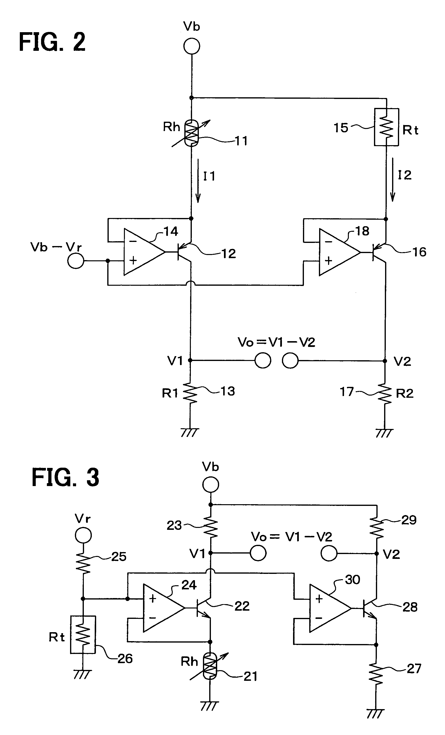
[0033]As shown in FIG. 2, an airflow sensor comprises a heater resistor 11, a PNP transistor 12, a resistor 13 and an operational amplifier 14. The heater resistor 11 is connected to the emitter of the PNP transistor 12 and the resistor 13 is connected to the collector of the PNP transistor 12 to form a series circuit including the heater resistor 11, the PNP transistor 12 and the resistor 13 along a first current path. A power supply Vb supplies a current to the first current path.
[0034]An electrical potential appearing at a junction between the heater resistor 11 and the emitter of the PNP transistor 12 is supplied to an inverting input terminal of the operational amplifier 14. On the other hand, a constant voltage (Vb−Vr) lower than the power supply Vb by a predetermined voltage Vr is supplied to a non-inverting input terminal of the operational amplifier 14. An electrical potential appearing at the output terminal of the operational amplifier 14 is supplied to...
third embodiment
(Third Embodiment)
[0040]As shown in FIG. 3, an airflow sensor comprises a heater resistor 21, an NPN transistor 22, a resistor 23 and an operational amplifier 24. The heater resistor 21, the NPN transistor 22, the resistor 23 and the operational amplifier 24 are connected to each other in the same configuration as the first embodiment shown in FIG. 1 except that an electrical potential obtained by division of a constant voltage Vr through a voltage divider comprising a resistor 25 and a temperature detection resistor 26 is supplied to a non-inverting input terminal of the operational amplifier 24. Thus, the temperature detection resistor 26 is capable of compensating a detected flow rate of the fluid for an error generated in the detected flow rate as a flow-rate change reflected in a characteristic representing a relation between the flow rate and the temperature of the fluid.
[0041]In addition, the airflow sensor further comprises a resistor 27, an NPN transistor 28, a resistor 29 ...
PUM
 Abstract
Description
Claims
Application Information
 - R&D
- Intellectual Property
- Life Sciences
- Materials
- Tech Scout
- Unparalleled Data Quality
- Higher Quality Content
- 60% Fewer Hallucinations
Browse by: Latest US Patents, China's latest patents, Technical Efficacy Thesaurus, Application Domain, Technology Topic, Popular Technical Reports.
© 2025 PatSnap. All rights reserved.Legal|Privacy policy|Modern Slavery Act Transparency Statement|Sitemap|About US| Contact US: help@patsnap.com


