
Apparatus and method for conditional instruction execution

a conditional instruction and applicability technology, applied in the field of microelectronics, can solve the problems of limiting the use of programable instructions, affecting the operation of the operation, and a great deal of complexity in the present day microprocessor, so as to achieve the effect of preventing the operation from being executed

Active Publication Date: 2006-12-26
IP FIRST +1
View PDF11 Cites 12 Cited by
  • Summary
  • Abstract
  • Description
  • Claims
  • Application Information

AI Technical Summary

Benefits of technology

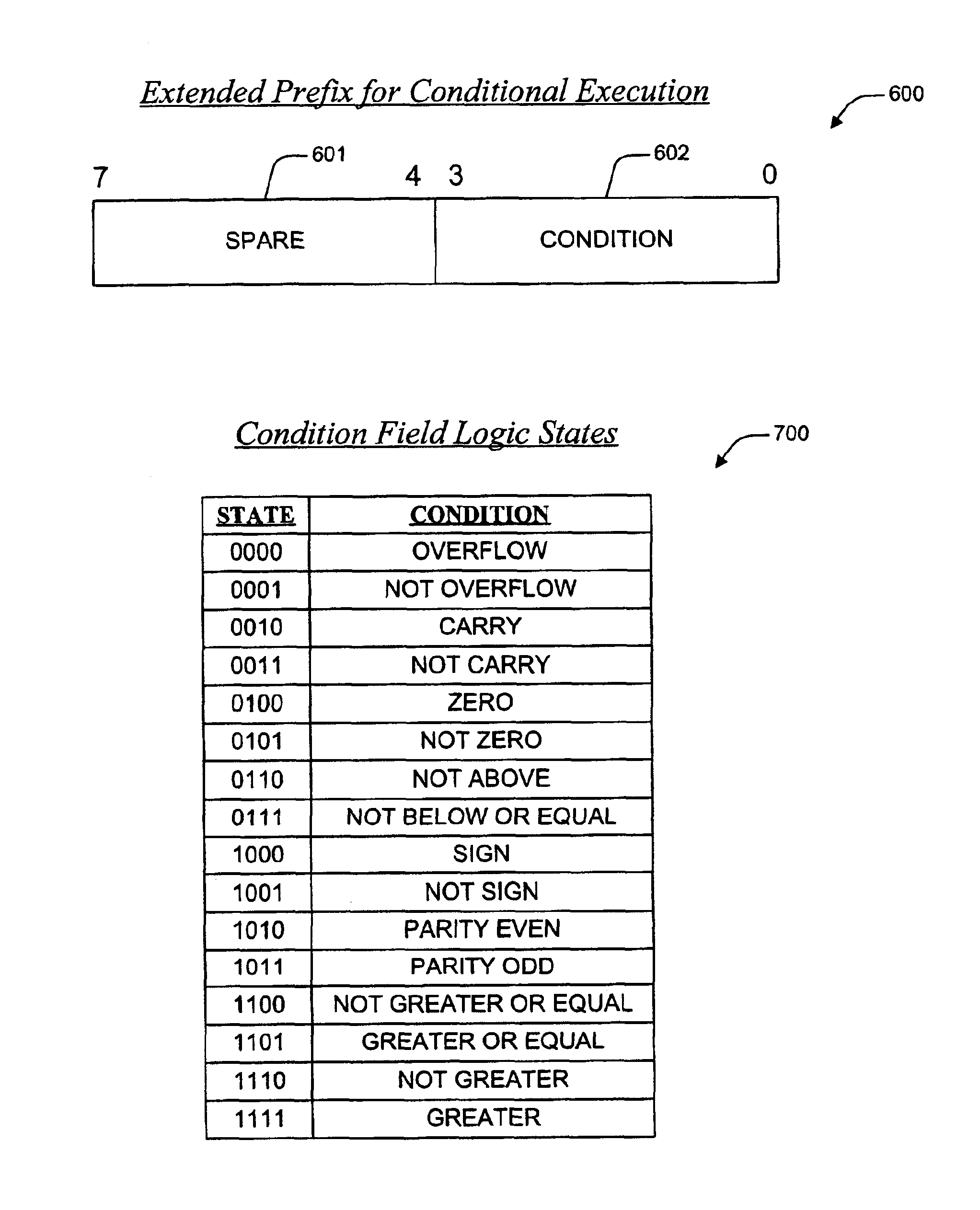
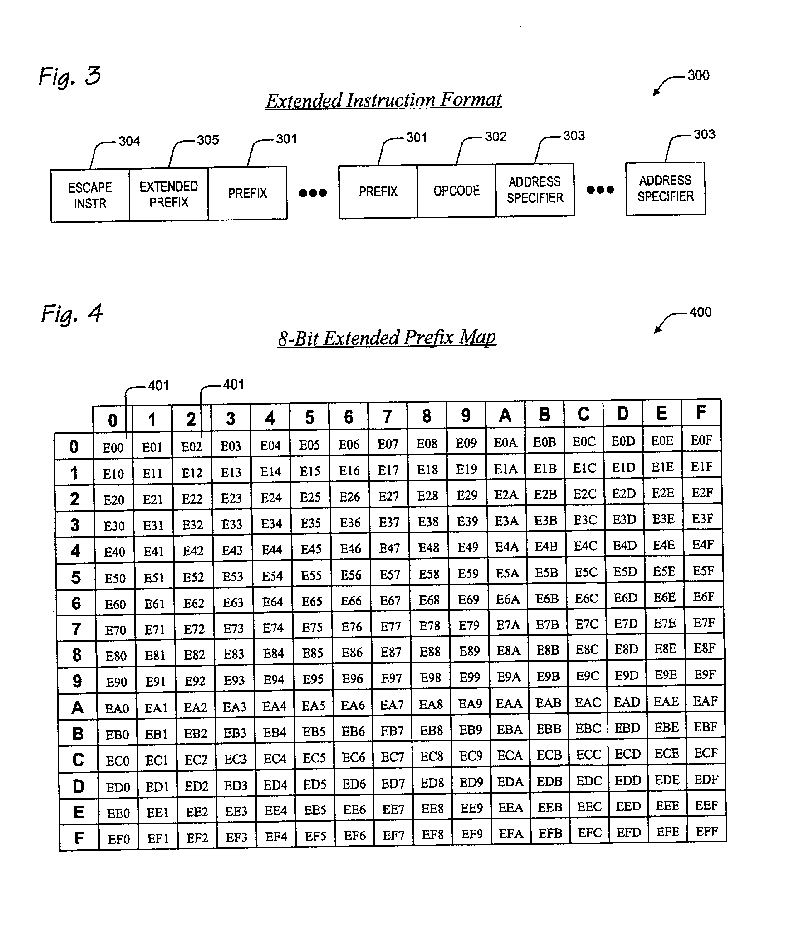
[0014]The present invention, among other applications, is directed to overcoming these and other problems and disadvantages of the prior art. The present invention provides a superior technique for extending a microprocessor instruction set beyond its current capabilities to provide comprehensive conditional execution features. In one embodiment, a conditional execution apparatus in a microprocessor is provided. The conditional execution apparatus includes translation logic and extended execution logic. The translation logic translates an extended instruction into corresponding micro instructions. The extended instruction has and extended...

Problems solved by technology

Quite frankly, a present day microprocessor is an amazingly complex and capable machine in comparison to its 30-year-old predecessors.
This factor, legacy compatibility, moreover accounts for a great deal of complexity in a present day microprocessor.
Yet, while in the past developers have been able to incorporate newly developed architectural features into existing instruction set architectures, the means whereby use of these features is enabled-programmable instructions-are becoming scarce.

Method used


Image

  • Apparatus and method for conditional instruction execution
  • Apparatus and method for conditional instruction execution
  • Apparatus and method for conditional instruction execution

Examples


Embodiment Construction

[0030]The following description is presented to enable one of ordinary skill in the art to make and use the present invention as provided within the context of a particular application and its requirements. Various modifications to the preferred embodiment will, however, be apparent to one skilled in the art, and the general principles discussed herein may be applied to other embodiments. Therefore, the present invention is not intended to be limited to the particular embodiments shown and described herein, but is to be accorded the widest scope consistent with the principles and novel features herein disclosed.

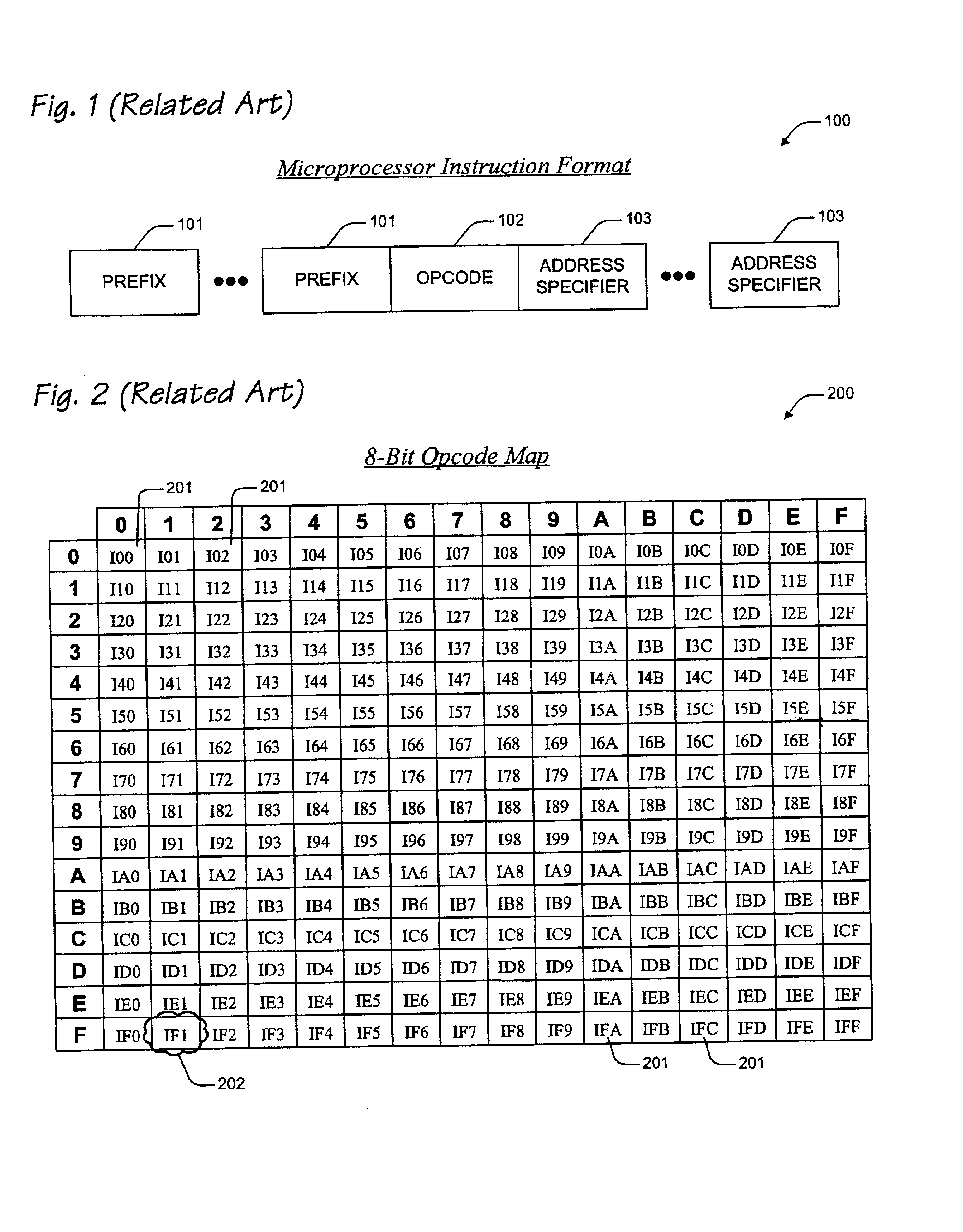
[0031]In view of the above background discussion on the techniques employed within present day microprocessors to extend the architectural features of those microprocessors beyond the capabilities of their associated instruction sets, a related art example will now be discussed with reference to FIGS. 1-2. The discussion highlights the dilemma that microprocessor designers ro...


PUM


Abstract

A conditional execution apparatus in a microprocessor is provided. The conditional execution apparatus includes translation logic and extended execution logic. The translation logic translates an extended instruction into corresponding micro instructions. The extended instruction has and extended prefix and an extended prefix tag. The extended prefix specifies a condition, where execution of an operation prescribed by the extended instruction depends upon realization of the condition. The extended prefix tag indicates the extended prefix, where the extended prefix tag is an otherwise architecturally specified opcode within an instruction set for the microprocessor. The extended execution logic is coupled to the translation logic. The extended execution logic receives the corresponding micro instructions, and evaluates the condition. If the condition is not realized, then the extended execution logic precludes execution of the operation.

Description

CROSS-REFERENCE TO RELATED APPLICATIONS[0001]This application claims priority based on U.S. Provisional Application, Ser. No. 60 / 369,570, filed Apr. 2, 2002, entitled “APPARATUS AND METHOD FOR CONDITIONAL INSTRUCTION EXECUTION.”[0002]This application is related to the following co-pending U.S. Patent Applications, which are filed on the same day as this application, and which have a common assignee and common inventors.[0003]SERIALDOCKETNUMBERNUMBERTITLE10 / 144,595CNTR.2176APPARATUS AND METHOD FOREXTENDING A MICROPROCESSORINSTRUCTION SET10 / 144,593CNTR.2188APPARATUS AND METHOD FORSELECTIVE CONTROL OFCONDITION CODE WRITE BACK10 / 144,590CNTR.2189MECHANISM FOR EXTENDINGTHE NUMBER OF REGISTERSIN A MICROPROCESSOR10 / 144,589CNTR.2198APPARATUS AND METHOD FORSELECTIVE CONTROL OFRESULTS WRITE BACKBACKGROUND OF THE INVENTION[0004]1. Field of the Invention[0005]This invention relates in general to the field of microelectronics, and more particularly to a technique for incorporating conditional exe...

Claims


Application Information

Patent Timeline
IPC IPC(8): G06F9/38G06F9/00G06F9/318
CPCG06F9/30174G06F9/30185G06F9/30189G06F9/3842
Inventor HENRY, G. GLENNHOOKER, RODNEY E.PARKS, TERRY
Owner IP FIRST
Learn More