
Methods and systems for automatically configuring network monitoring system

a network monitoring and automatic configuration technology, applied in the field of network monitoring systems, can solve the problems of manual configuration of the system, unsatisfactory use of external link probes and monitoring units, and the occupying of space in the telecommunications network facilities, etc., and achieve the effect of reducing the amount of labor

Active Publication Date: 2006-12-26
TEKELEC GLOBAL INC
View PDF28 Cites 110 Cited by
  • Summary
  • Abstract
  • Description
  • Claims
  • Application Information

AI Technical Summary

Benefits of technology

This patent describes a way to automatically configure a network monitoring system when it detects new signals or if certain ones become unavailable. It does this by connecting different components together based on their capabilities and needs. By doing this, the system can quickly adjust its configurations without requiring excessive human effort. Overall, this technology makes it easier to manage changes in network traffic and improve overall efficiency.

Problems solved by technology

The technical problem addressed in this patent text is the need for a network monitoring system that requires less manual reconfiguration and can automatically adjust to changes in network configuration. The current systems are bulky and require significant amounts of space in network facilities, and the reconfiguration process is time-consuming and often results in the monitoring system being out of sync with the network being monitored.

Method used


Image

  • Methods and systems for automatically configuring network monitoring system
  • Methods and systems for automatically configuring network monitoring system
  • Methods and systems for automatically configuring network monitoring system

Examples


Embodiment Construction

System Overview

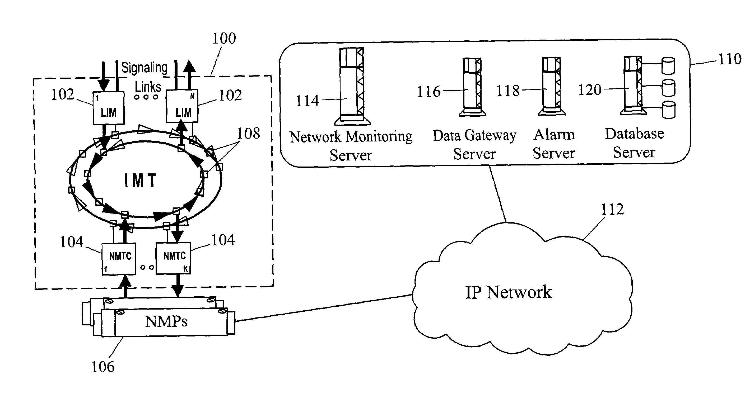
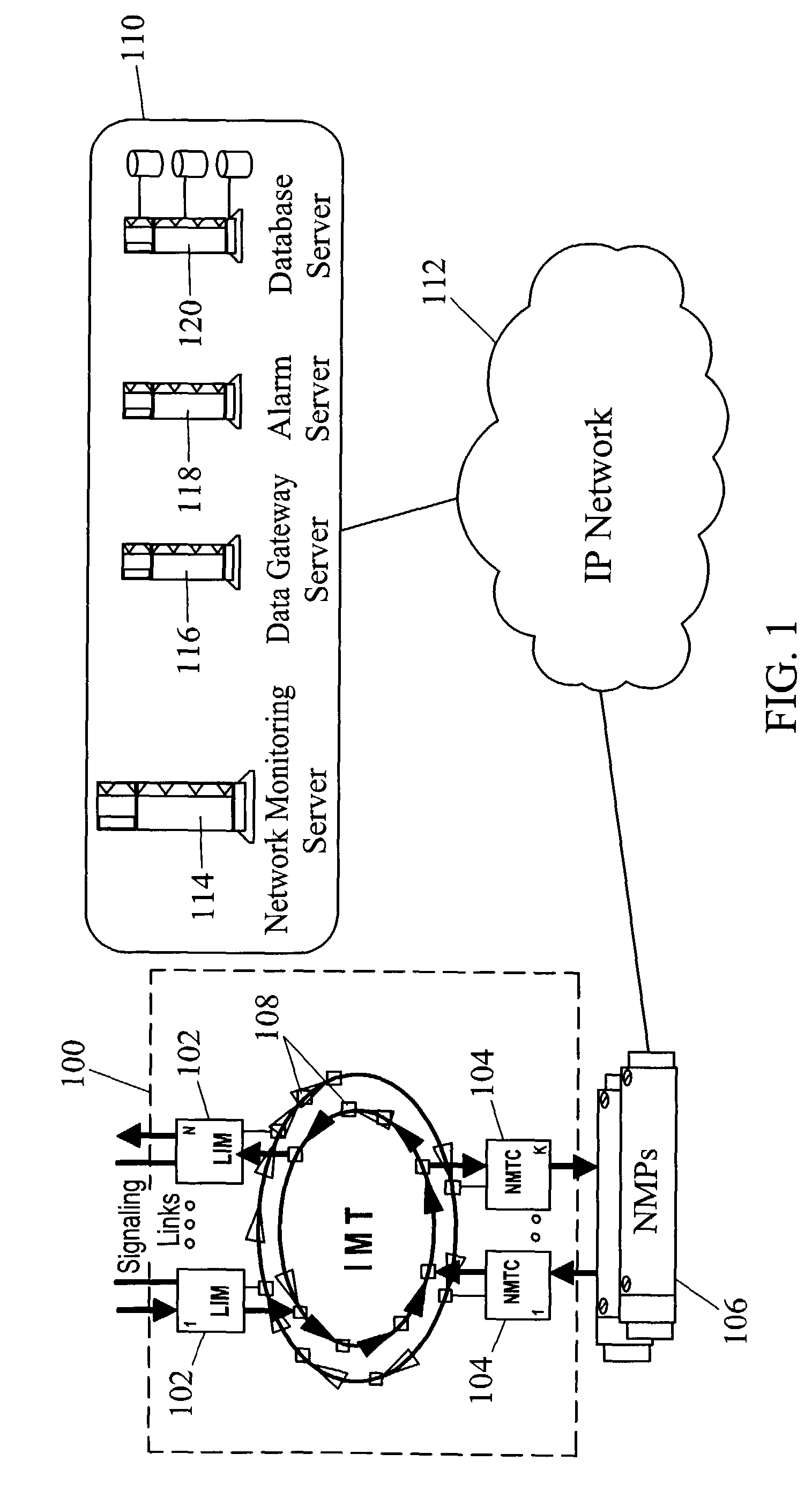
[0037]In one embodiment, an automatically configurable network monitoring system according to the present invention may integrated within a network routing node, such as a signal transfer point or an SS7 / IP gateway. FIG. 1 illustrates an exemplary architecture for an integrated automatically configurable network monitoring system according to an embodiment of the present invention. In FIG. 1, reference numeral 100 represents a routing node, such as an STP or an SS7 / IP gateway. Routing node 100 includes a plurality of link interface modules (LIMs) 102 that send and receive SS7 messages via SS7 signaling links. Although not illustrated in FIG. 1, routing node 100 may also include data communication modules (DCMs) for sending and receiving IP messages via IP signaling links. Network monitoring transport cards (NMTCs) 104 route messages between LIMs 102 and network monitoring processors (NMPs) 106. LIMs 102 and NMTCs 104 are connected via IMT buses 108. NMPs 106 buffer MS...


PUM


Abstract

An automatically configurable network monitoring system includes a network monitoring communications protocol used for communications between a network monitoring client executing on a routing node (100) being monitored and a network monitoring server executing on a network monitoring processor (106). According to the network monitoring communications protocol, the network monitoring client broadcasts a network monitoring service request message to the network monitoring servers. The service request message identifies a signaling link for which network monitoring service is being requested. The network monitoring servers provisioned to the requested provide network monitoring service respond affirmatively and thereby automatically grant network monitoring service. The network monitoring system may be completely probeless or, alternatively, used in conjunction with probe-based network monitoring devices.

Description


Claims


Application Information

Patent Timeline
Owner TEKELEC GLOBAL INC
Learn More