Circuit arrangement for operating at least one light source
a circuit arrangement and light source technology, applied in the direction of electric variable regulation, process and machine control, instruments, etc., can solve the problems of the problem of not being able to adhere to the relevant standards for the line current harmonic, and the limitation value of line current harmonics. to achieve the effect of further reducing the factor produced during the operation of the lamp
- Summary
- Abstract
- Description
- Claims
- Application Information
AI Technical Summary
Benefits of technology
Problems solved by technology
Method used
Image
Examples
Embodiment Construction
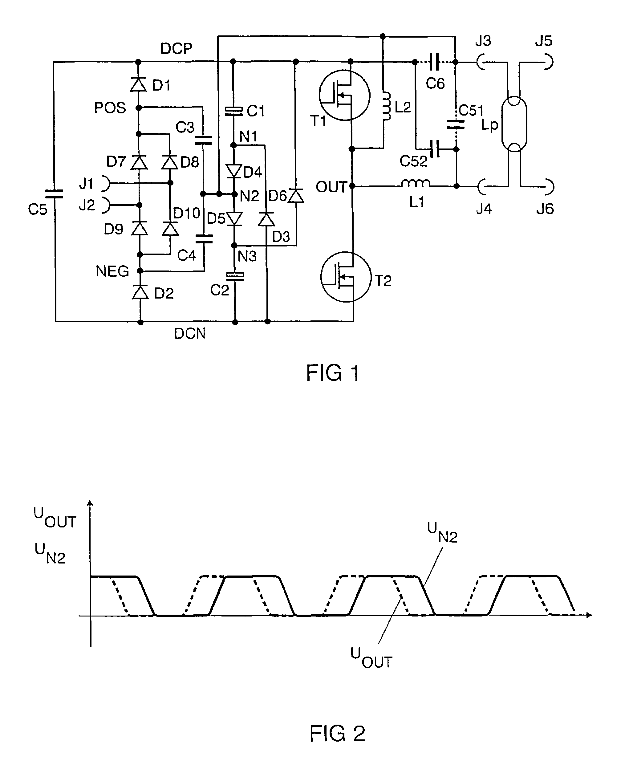
[0040]In the text which follows, transistors will be denoted by the letter T, diodes by the letter D, capacitors by the letter C, inductors by the letter L, resistors by the letter R and connections by the letter J, in each case followed by a number.
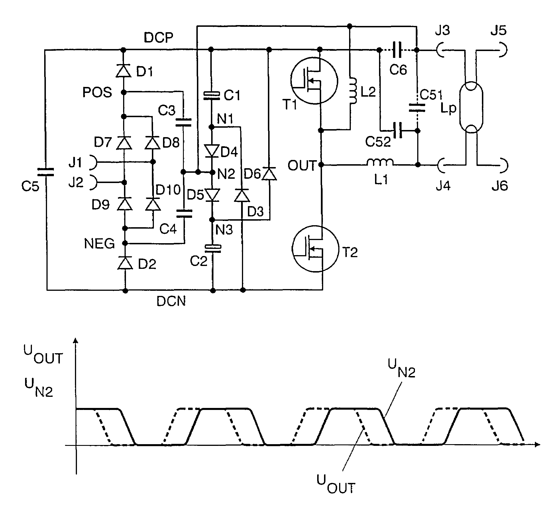
[0041]FIG. 1 shows an exemplary embodiment of the invention for a fluorescent lamp having electrode filaments. The connections J1 and J2 form the system voltage input. A system voltage can be connected to J1 and J2. J1 and J2 are connected to the input of a rectifier. Means for radio interference suppression may also be connected upstream of the rectifier.
[0042]In general, the rectifier comprises a known bridge circuit comprising the rectifier diodes D7, D8, D9 and D10 which make the rectified system voltage available at their positive rectifier output POS and their negative rectifier output NEG. Owing to the charge pump, the rectifier diodes need to be able to be switched at a high frequency. It is also possible for slow rectifier diode...
PUM
 Abstract
Description
Claims
Application Information
 - R&D
- Intellectual Property
- Life Sciences
- Materials
- Tech Scout
- Unparalleled Data Quality
- Higher Quality Content
- 60% Fewer Hallucinations
Browse by: Latest US Patents, China's latest patents, Technical Efficacy Thesaurus, Application Domain, Technology Topic, Popular Technical Reports.
© 2025 PatSnap. All rights reserved.Legal|Privacy policy|Modern Slavery Act Transparency Statement|Sitemap|About US| Contact US: help@patsnap.com


