
Hardening method and apparatus utilizing laser beams

a laser beam and hardening method technology, applied in the field of hardening methods and equipment utilizing laser beams, can solve the problems of deterioration in hardening (hardened) quality, requiring a lot of time and labor, and reducing the service life of equipment, so as to eliminate defects or drawbacks.

Inactive Publication Date: 2006-12-26
THK CO LTD
View PDF7 Cites 7 Cited by
  • Summary
  • Abstract
  • Description
  • Claims
  • Application Information

AI Technical Summary

Benefits of technology

[0005]An object of the present invention is therefore to substantially eliminate defects or drawbacks encountered in the prior art mentioned above and to provide a laser beam hardening method and apparatus capable of irradiating, with laser beam, a material having portions, in form of a plurality of rows, to be hardened which are influenced by each other.
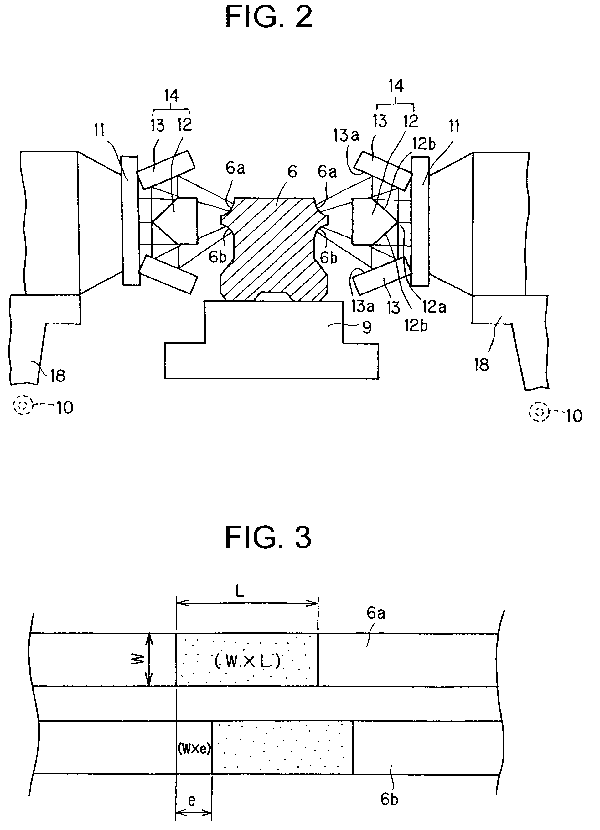
[0006]The above object can be achieved, according to the present invention, generally by making longer, in a sectional plane perpendicular to an optical axis of the laser beam, a length of an laser beam irradiation shape in the longitudinal direction of the portion to be hardened than a length thereof in a direction perpendicular to the longitudinal direction at a time when a plurality of laser beams irradiate a plurality of rows of portions to be hardened which are mutually thermally influenced.
[0011]According to this hardening method, there is not caused any problem or inconvenience, which may be caused at a time when a plurality of rows of portions to be hardened are hardened or quenched with a time difference, for example, inconvenience that a hardened layer of one hardened portion is softened by heat (thermal energy) application to another one portion to be hardened. Furthermore, since the plural portions to be hardened are influenced on each other at the time of heat applications thereto, the total energy required for heating the portions to be hardened can be relatively eliminated in comparison with a case that the hardening processes to the plural portions are performed with a time difference.
[0012]In addition, although the laser beams irradiating the plural portions to be hardened are set so as to accord with each other as much as possible so as not to cause a positional deviation in the laser beam moving direction, there is a case of causing the positional deviation by a certain reason. In a case where the total energy to be applied to the portions to be hardened is equal, an energy of a deviated portion (“e” see FIG. 3) between the two parallel laser beams can be reduced by making longer the length of the laser beam irradiation shape in the longitudinal direction of the portion to be hardened than the length thereof in the direction perpendicular to the longitudinal direction. Accordingly, the problem or inconvenience caused in the case that the hardening process is performed to the plural portions with time difference can be effectively eliminated.
[0014]The laser diode generally emits a laser beam having a elongated rectangular shape, and accordingly, it is easy to make longer the length of the laser beam irradiation shape in the longitudinal direction of the portion to be hardened than the length thereof in the direction perpendicular to the longitudinal direction.
[0016]According to such preferred embodiment, the track member is less bent even by the hardening process.

Problems solved by technology

This hardening method requires two times of laser beam irradiation, thus requiring much time and labor.
In addition to this defect, there may cause a case that the hardened layer 2a of the one of the ball rolling surfaces 1a which was once hardened (first time hardening) is again heated and softened (in a state as shown by a reference numeral 3 in FIG. 9) by the second time laser beam irradiation, or cause a case that a work distance in the second-pass is shifted by the strain caused at the first-pass time, which will result in deterioration in hardening (hardened) quality, thus also providing defects.

Method used


Image

  • Hardening method and apparatus utilizing laser beams
  • Hardening method and apparatus utilizing laser beams
  • Hardening method and apparatus utilizing laser beams

Examples


Embodiment Construction

[0034]Hardening method and apparatus utilizing laser beams according to the present invention are utilized for a hardening process in which the laser beam irradiates a raw or base material (which is called hereinlater merely “material”) having a plurality of rows of portions to be hardened which are influenced on each other. As such material, there will be listed, for example, a track member of a motion guide apparatus such as a liner guide, a ball spline or a ball screw.

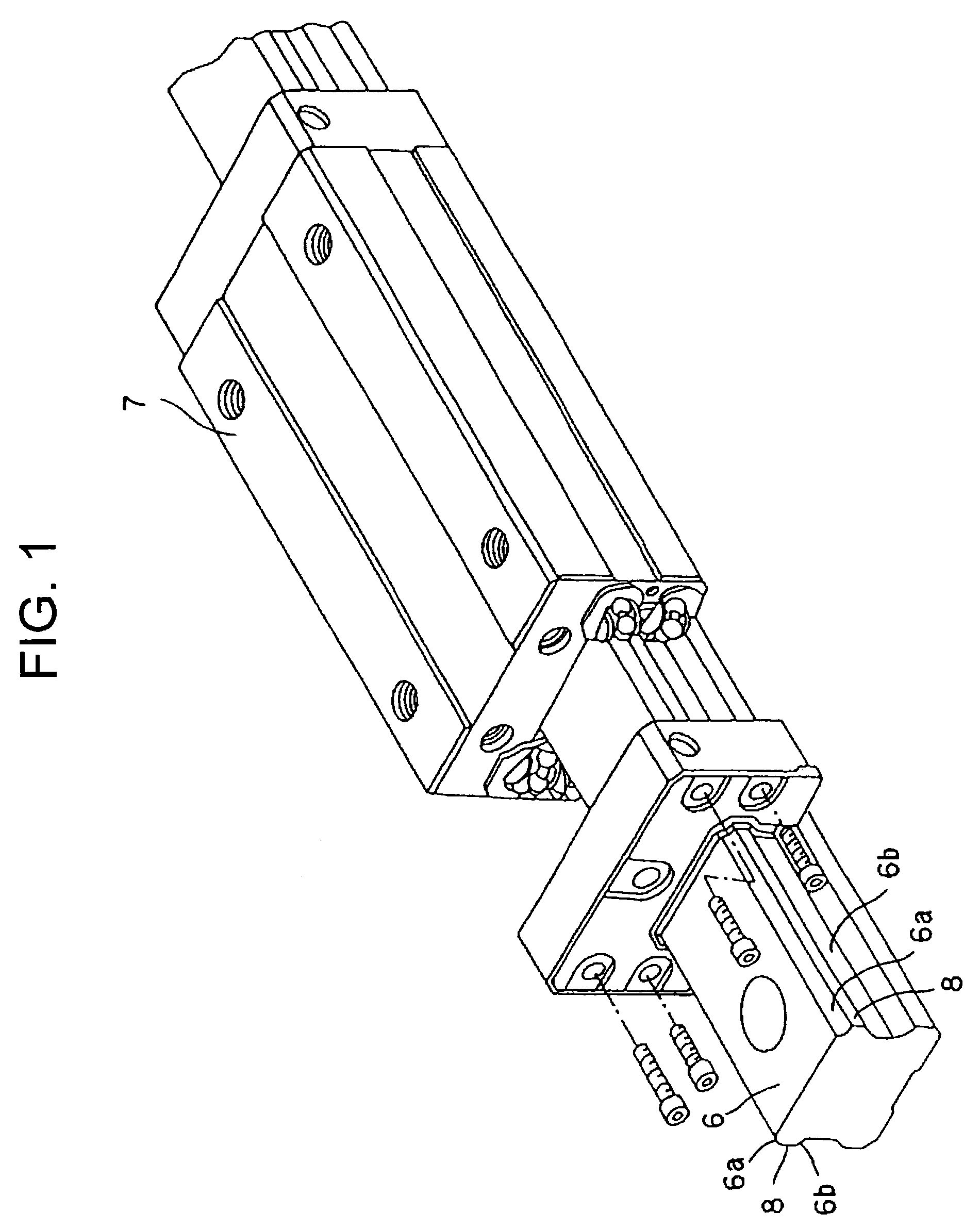
[0035]With reference to FIG. 1 representing a linear guide, the linear guide comprises a track member 6 having an elongated scale and a movable member 7 relatively linearly movable with respect to the track member 6. The track member 6 is formed with a plurality of ball rolling grooves 6a, 6a, 6b, 6b as a plurality of rolling member rolling surfaces each extending in the longitudinal direction of the track member 6. On the other hand, the movable member 7 is formed with a plurality of ball circulation passages inclu...


PUM

PropertyMeasurementUnit
lengthaaaaaaaaaa
temperatureaaaaaaaaaa
energy densityaaaaaaaaaa

Abstract

A material, such as track member for a linear motion guide, having a plurality of rows of portions to be hardened which are thermally influenced on each other, is hardened by emitting laser beams so as to simultaneously irradiate a plurality of rows of portions of the material to be hardened, and moving the laser beams irradiating the rows of portions to be hardened relatively in a longitudinal direction of the portions to be hardened. In this hardening process, the laser beam irradiation is performed such that, in a sectional plane perpendicular to an optical axis of the laser beam, a length of a laser beam irradiation shape in the longitudinal direction of the portion to be hardened is set to be longer than a length thereof in a direction perpendicular to the longitudinal direction.

Description

BACKGROUND OF THE INVENTION[0001]The present invention relates to hardening method and apparatus utilizing laser beams in which a laser beam irradiates a surface of a raw (or base) material.[0002]When the laser beam irradiates the surface of the base material, a temperature of the localized surface layer of the material rises to a temperature suitable for heat treatment in a short time by a heat source of high energy density of the laser beam. When the heating is stopped, the heat is transmitted inside the material and then the material is rapidly quenched, thus performing a hardening treatment or working. A hardening technology utilizing the laser beam can provide such advantages as that localized hardening process can be made only to a necessary portion of the material, and in addition, oil, water or the like is not required for cooling and only a small strain due to the heat treatment is caused.[0003]In prior art of certain technical field, a laser beam is utilized for irradiatio...

Claims


Application Information

Patent Timeline
Patent Type & Authority Patents(United States)
IPC IPC(8): C21D1/09B23K26/067C21D9/00
CPCB23K26/067B23K26/0673C21D1/09C21D9/0068C21D2221/00
Inventor YOSHII, TOSHIKAZU
Owner THK CO LTD
Learn More