
Magnetic contact tamper switch for security accessories

a technology of contact tamper switch and accessories, which is applied in the direction of mechanical actuation of burglar alarm, instruments, force/torque/work measurement apparatus, etc., can solve the problems of uneven stress in the pcb and/or enclosure or cover, unauthorized access to system components may be presumed as attacks on the system, fracture or failure, etc., to achieve the effect of improving the tamper detection switch

Inactive Publication Date: 2006-12-19
HONEYWELL INT INC
View PDF5 Cites 20 Cited by
  • Summary
  • Abstract
  • Description
  • Claims
  • Application Information

AI Technical Summary

Benefits of technology

The present invention provides an improved tamper detection switch for use in a security system component enclosure. The switch includes a conductive magnetic element and at least two ferrous metal contacts. When the enclosure is closed, the conductive magnetic element bridges the ferrous contacts and closes the tamper circuit, indicating a possible attack. The switch may be secured to the enclosure using various means such as a fastener, snap fit, friction fit, or living hinge. The ferrous contacts may be mounted on a circuit board or secured to the cover of the enclosure. The base of the enclosure may also include a cage to capture the conductive magnetic element. The technical effects of this invention include improved security and protection against tampering or unauthorized access to the enclosure.

Problems solved by technology

In particular, unauthorized access to system components may be presumed as attacks on the system.
Among these is the localized pressure on the switch causing uneven stress in the PCB and / or the enclosure or cover.
This may lead to fracture or failure with repeated opening and closing of the switch, cover, and / or enclosure.
Accordingly, the pressure sensitive switch may no longer be reliably closed due to the material creep.
Additionally, the surface to which the system component is mounted may be uneven, and not provide a reliable surface to actuate the pressure sensitive switch.
At least one drawback of this arrangement is the vulnerability of the reed switch.

Method used


Image

  • Magnetic contact tamper switch for security accessories
  • Magnetic contact tamper switch for security accessories

Examples


Embodiment Construction

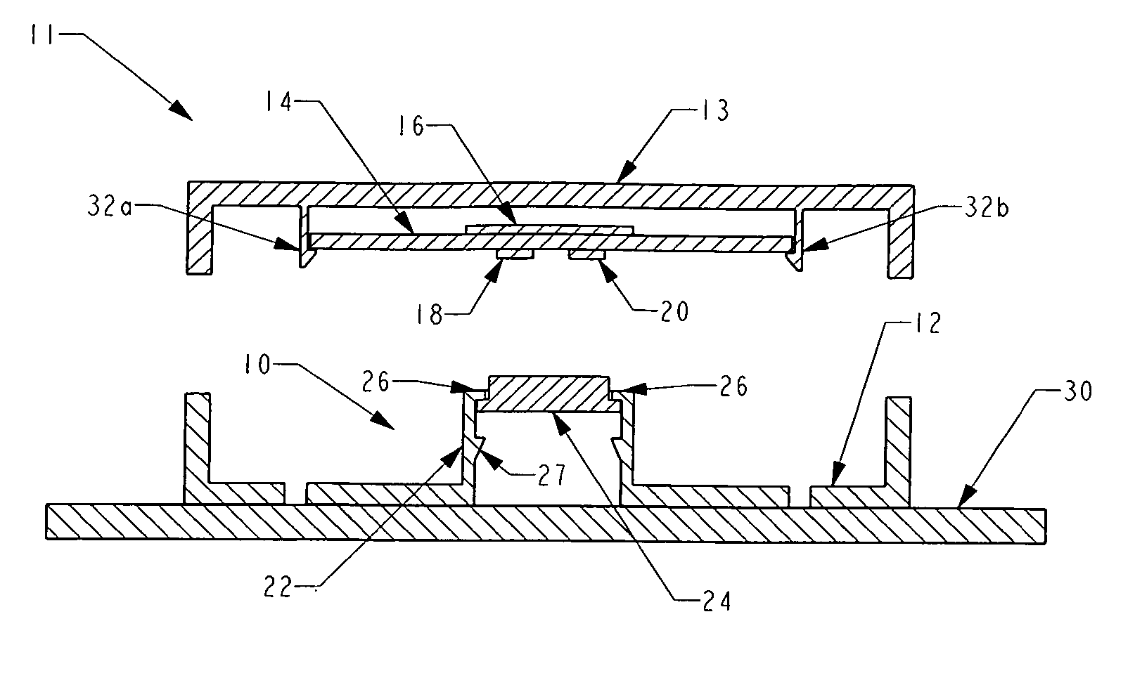
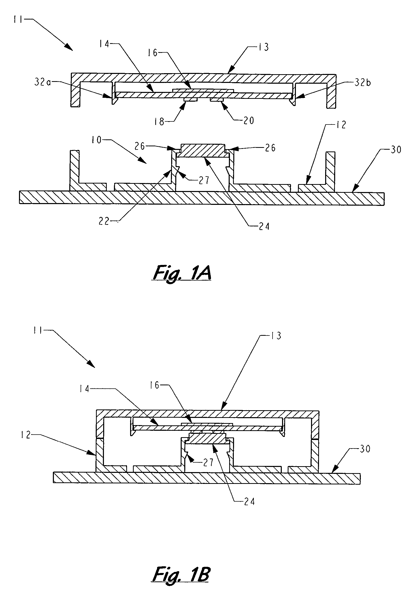
[0013]Referring now to FIG. 1A, illustrated in cross-section is a magnetic contact tamper switch, generally 10, in an open condition. The component 11 to be protected by the tamper switch 10 includes a base 12, a cover 13, and a circuit board 14. The component 11 may be closed (see FIG. 1B), by fixing cover 13 on base 12 for example by a fastener, friction fit, snap fit, or a mechanical or living hinge (none shown). In the closed position, the circuit board 14 is positioned between the base 12 and the cover 13. Optionally, the circuit board 14 may be secured to the cover 13, for example by snap fit projections 32a, 32b. Alternately, fasteners, adhesive, solvents, friction fits, or similar means known in the art may be employed to secure the circuit board 14 to the cover 13.

[0014]The circuit board 14 includes a tamper detection circuit 16. The tamper detection circuit 16 is open between two ferrous contacts, 18, 20. In this context, ferrous contacts shall include contacts comprising ...


PUM


Abstract

A tamper detection switch is primarily for use in an enclosure of a security system component. The enclosure has a base and a cover that may be repositioned relative to the base. One of the cover and the base holds a conductive magnetic element free to translate within a predetermined range generally perpendicular to the respective cover or base. The other of the cover and the base holds at least two ferrous metal contacts of an open tamper circuit in proximity of a conductive magnetic element. In the closed position the conductive magnetic element bridges the ferrous contacts and closes the tamper circuit. Attempts to tamper with the enclosure separate the ferrous contacts from the conductive magnetic element, opening the tamper circuit and signaling a possible attack.

Description

BACKGROUND OF THE INVENTION[0001]1. Field of Invention[0002]The invention relates to the field of security systems, and more particularly to a contact tamper switch for detecting attempts to tamper with components of a security system.[0003]2. Description of Related Art[0004]In the field of security systems it is known to provide some means to detect attempts to tamper with the system, for example as an attempt to disable or defeat it. In particular, unauthorized access to system components may be presumed as attacks on the system. In particular, components of the security system may be accessible by potential intruders while the security system is in an unarmed state. As an example, the system component may be located in a room open to the public during normal hours, while the security system is unarmed.[0005]In one embodiment, a circuit board, for example a printed circuit board (PCB), as an element of a security system component, is provided with a pressure-sensitive switch. A co...

Claims


Application Information

Patent Timeline
Patent Type & Authority Patents(United States)
IPC IPC(8): G08B21/00
CPCG08B29/046H01H9/085H01H36/00H01H2036/0086
Inventor WILSON, GEORGE N.LEE, ROBERT E.PIEL, KEVIN G.
Owner HONEYWELL INT INC
Learn More