
Equipment component monitoring and replacement management system

a technology for monitoring and managing the life cycle of equipment, applied in the field of equipment components monitoring and replacement management systems, can solve the problems of equipment failure, potentially life-threatening situations, severe and expensive secondary damage, etc., and achieve the effects of less or no increase in the probability of failure, improved equipment condition interpretation, and reduced cost of production

Active Publication Date: 2006-11-28
HYDRALIFT AMCLYDE INC
View PDF12 Cites 98 Cited by
  • Summary
  • Abstract
  • Description
  • Claims
  • Application Information

AI Technical Summary

Benefits of technology

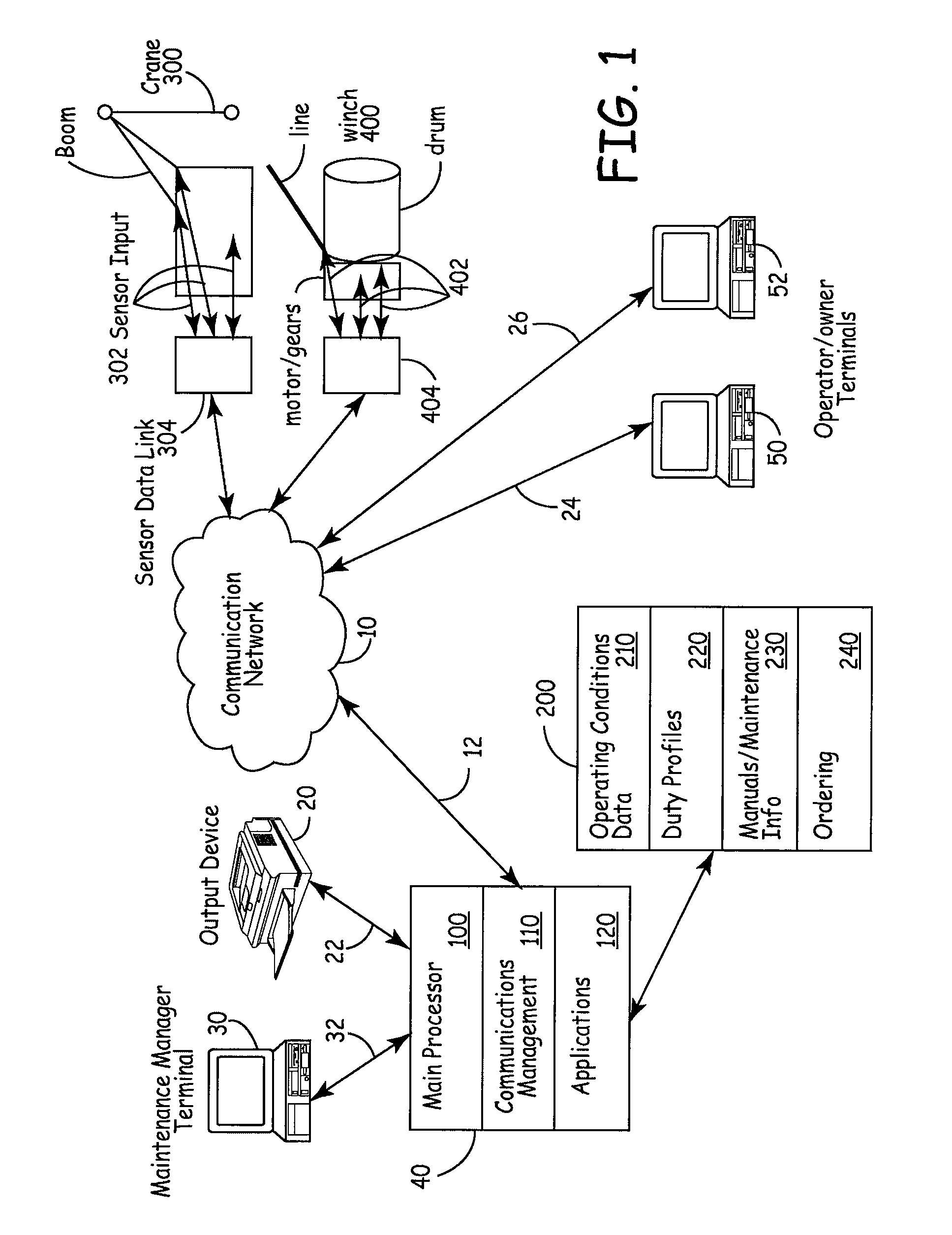
[0009]Yet another embodiment of the present invention provides an automated web-based service designed to let clients interface online or offline with any drilling equipment coupled to the system. On-site operators or personnel remote from the site, e.g., the headquarters of the company; can utilize information and knowledge stored among huge amounts of data. A part of the concept is to acquire and redirect existing equipment instrumentation signals into a centralized database. By also applying corporate knowledge about the equipment, like theoretical models, diagnostic algorithms, statistics, work load accumulation, etc, a service provider can provide value added data back to the company operating the equipment. The system may deliver last hour statistics from one specific machine, or advanced diagnostic algorithms applied across equipment operated by different companies. The system may help pinpointing potential areas for improved performance as well as assisting in predicting and planning on-demand maintenance.
[0010]There are two main approaches to equipment condition analysis. One is based on advanced engineering and mathematical modeling, which provide a reference for comparing measured operational data with theoretical data. The second, more common approach is that there is no known reliable model or theoretical knowledge for operation and wear on the equipment. In that case, empirical analysis of trends and patterns in large amounts of collected data, from a large number of equipment units, may over time provide better and better interpretation of equipment conditions.
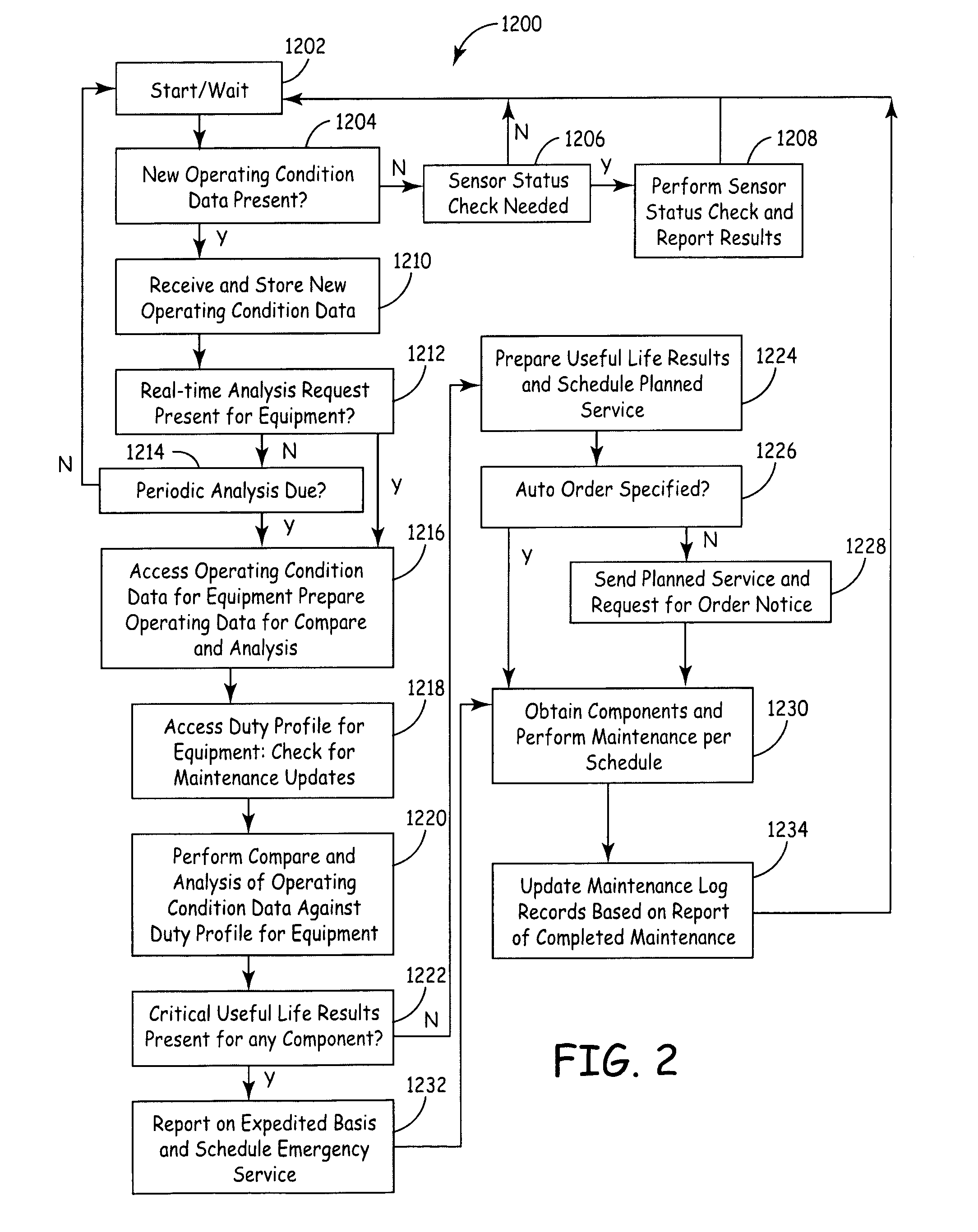
[0011]Whatever method is used, better condition models will enable calculation of weighted equipment use, i.e., use measured not just by time or repetitions of the operations but based on load or other conditions that effect equipment life. Obviously, there is a huge difference between 1000 running hours with heavy load and 1000 running hours without load at all. Some parts wear faster with certain operating conditions, e.g. higher speeds, others with different conditions, e.g., higher load. It is possible to define a “wear-map” for each component of any machine. By combining this wear-map with operational data, a figure for remaining lifetime can be estimated for wear parts. This will form the basis for a Reliability Centered Maintenance (RCM) approach, where from current condition and remaining lifetime data, one can dynamically estimate service and inspection intervals and spare part requirements. This provides for longer service and inspection intervals with little or no increase in chances of failure. Reliability and safety can also be improved.

Problems solved by technology

In modern machinery, such as marine machines, cranes, automatic transmissions, turboshaft engines, paper mills, rolling mills, aircraft engines, helicopter transmissions, and high-speed process machinery, failure of bearings, gears and other equipment frequently result in costly productivity loss, severe and expensive secondary damage, and potentially life threatening situations.
Equipment failures occur because, over time, gear / bearing assemblies and other parts that are stressed experience wear and damage, such as spalled bearing rolling elements, pitting on gear teeth, and bearing race damage.
However, wear factors such as load magnitudes, displacement distances, time periods under load, and speeds of displacement may heavily influence equipment wear and damage.
Consequently, when the wear factors are above normal for a significant period of time, the equipment can prematurely fail.
On the other hand, when the wear factors are minimal for a significant period of time, simply relying on periods of use to trigger component replacement can increase the costs of operation.
This is because useful component life is wasted, costs are increased due to more frequent maintenance, and productivity is decreased due to more frequent maintenance shutdowns.

Method used


Image

  • Equipment component monitoring and replacement management system
  • Equipment component monitoring and replacement management system
  • Equipment component monitoring and replacement management system

Examples


Embodiment Construction

A. Equipment Design and Component Useful Life

[0076]When sophisticated equipment is designed, it is frequently defined with a planned useful life for the overall item of equipment. In reality, the design must take into consideration the useful life of a variety of components. For components that are critical to useful life, there is usually useful life data available from a manufacturer or other source that has actual test data on useful life and / or theoretical projections that are derived from actual useful life data. Typically, the useful life is specified for one or more defined, assumed operating conditions. An operating condition may be specified in terms of a rate, such as speed or load, and a time duration for experiencing that speed or load and / or a distance for maintaining the rate of work, but may also include other operating conditions, such as environmental factors that may affect useful life, e.g., operating temperature, humidity, corrosives or particulates present. The ...


PUM


Abstract

A computer system for managing replacement components for equipment having a plurality of components, each component having a limited useful life, has a computer program module defining a duty profile comprising a plurality of usage cases for the equipment, each usage case involving two or more of the components and specified operating conditions for the involved components during execution of the usage cases. A further program module determines a theoretical useful life for each component involved in a duty profile, based on component useful life data under specified operating conditions; and sensors determine and monitor the occurrence of equipment operation corresponding to a usage case and measur actual operating conditions and number of operations. A further program module computes an adjusted theoretical useful life for a component experiencing operations, based on a comparison of actual operating conditions to those assumed for the usage case.

Description

CROSS-REFERENCE RELATED APPLICATIONS[0001]This application claims priority to U.S. Provisional Application No. 60 / 512,108, filed on Oct. 17, 2003 and U.S. Provisional Application No. 60 / 567,705, filed on May 3, 2004, the contents of both applications are hereby incorporated in their entirety by reference.BACKGROUND OF THE INVENTION[0002]The present invention relates to apparatus and methods for monitoring and managing the life cycle of equipment. More specifically, the present invention relates to apparatus and methods for predicting preventive maintenance periods and component replacement needs.[0003]Machinery requires periodic diagnostic maintenance to detect machine part wear, predict failure, and locate problems. In modern machinery, such as marine machines, cranes, automatic transmissions, turboshaft engines, paper mills, rolling mills, aircraft engines, helicopter transmissions, and high-speed process machinery, failure of bearings, gears and other equipment frequently result ...

Claims


Application Information

Patent Timeline
Patent Type & Authority Patents(United States)
IPC IPC(8): G06F17/00G01M13/00G06FG06F11/30G06F15/00
CPCG05B19/4065G05B19/4184G05B2219/34477G05B2219/37253G05B2219/37254G05B19/406G05B19/418G05B23/02G06F11/30G06F15/00F04D7/04F04D15/0088Y02P90/02G06Q50/04G06F15/025G06Q10/20
Inventor LONG, WAYNE R.BOOTH, MICHAEL L.WALLER, AARON D.HOLME, ANDERSORKE, PER REIDARFRAFJORD, ERIKGJEDEBO, JON GRUDE
Owner HYDRALIFT AMCLYDE INC
Learn More