
Latching mechanism for magnetically actuated micro-electro-mechanical devices

a magnetic actuator and latching mechanism technology, applied in the field of micro-electromechanical devices, can solve the problems of increasing the cost of operating the switch, requiring continuous power to retain functionality, and the mirrors in the array that have been actuated from a rest position are not stable, so as to reduce the voltage needed to move the mirrors, strengthen the magnetic field, and reduce the effect of the voltage needed

Inactive Publication Date: 2006-11-28
CORNING INC
View PDF18 Cites 10 Cited by
  • Summary
  • Abstract
  • Description
  • Claims
  • Application Information

AI Technical Summary

Benefits of technology

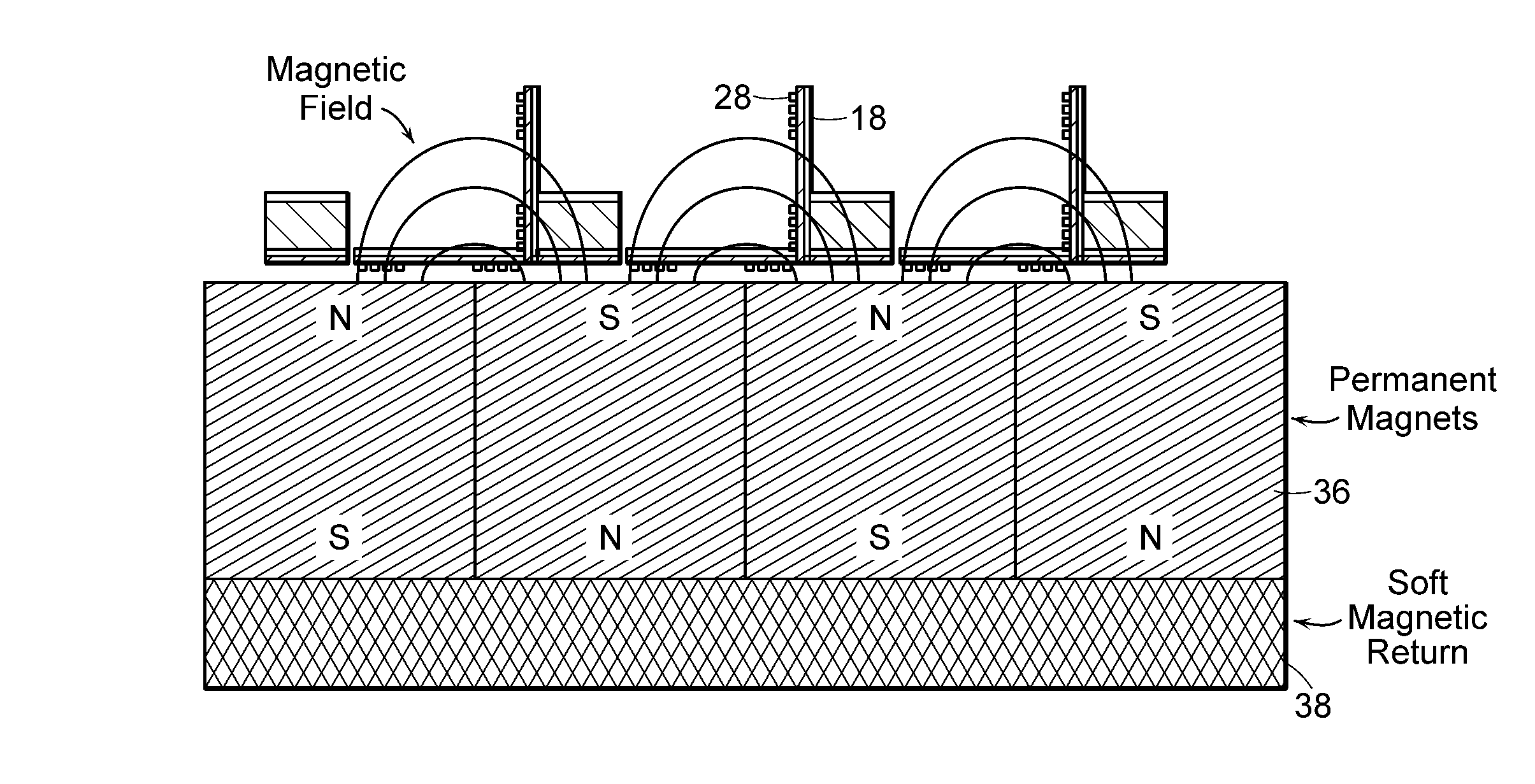
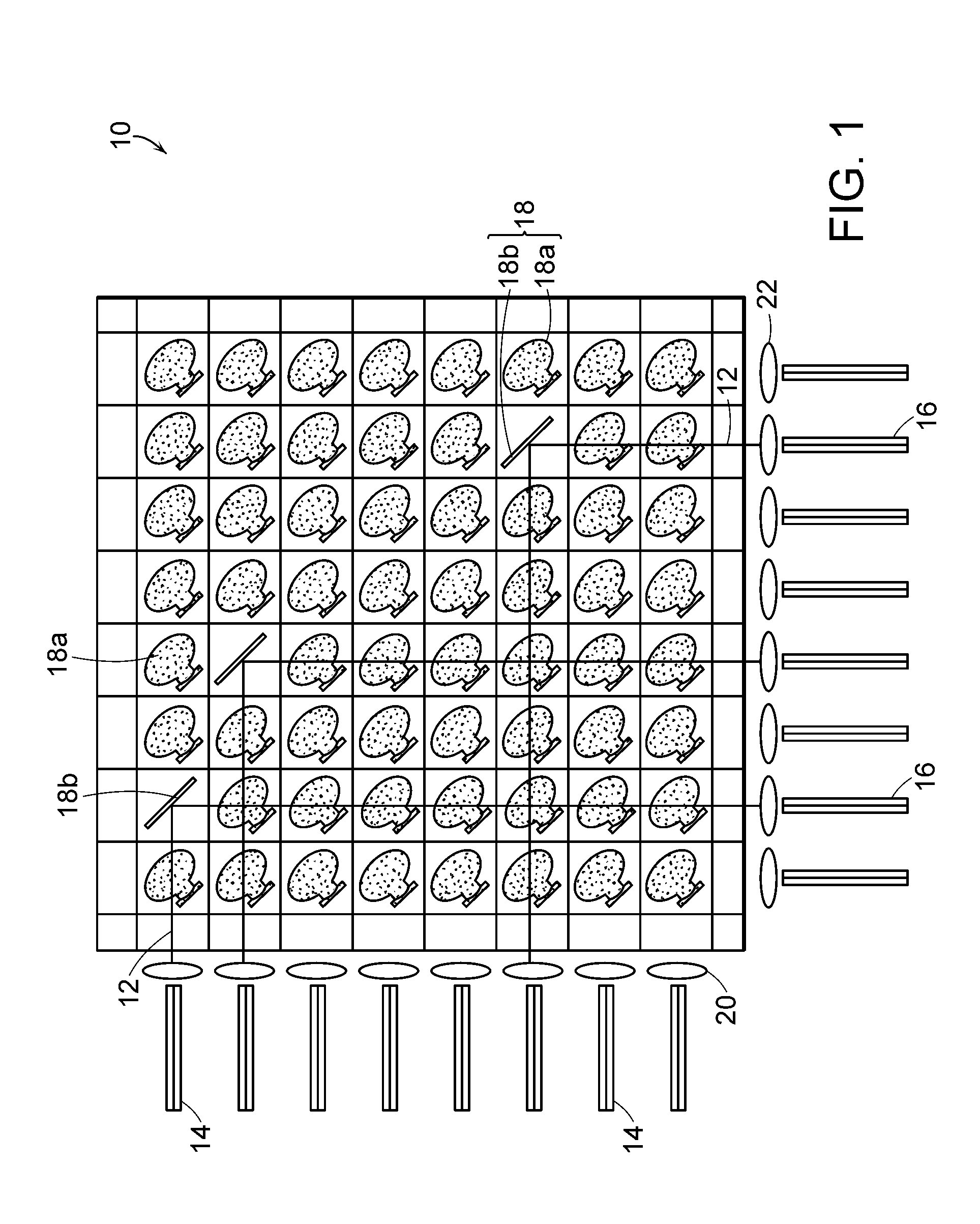
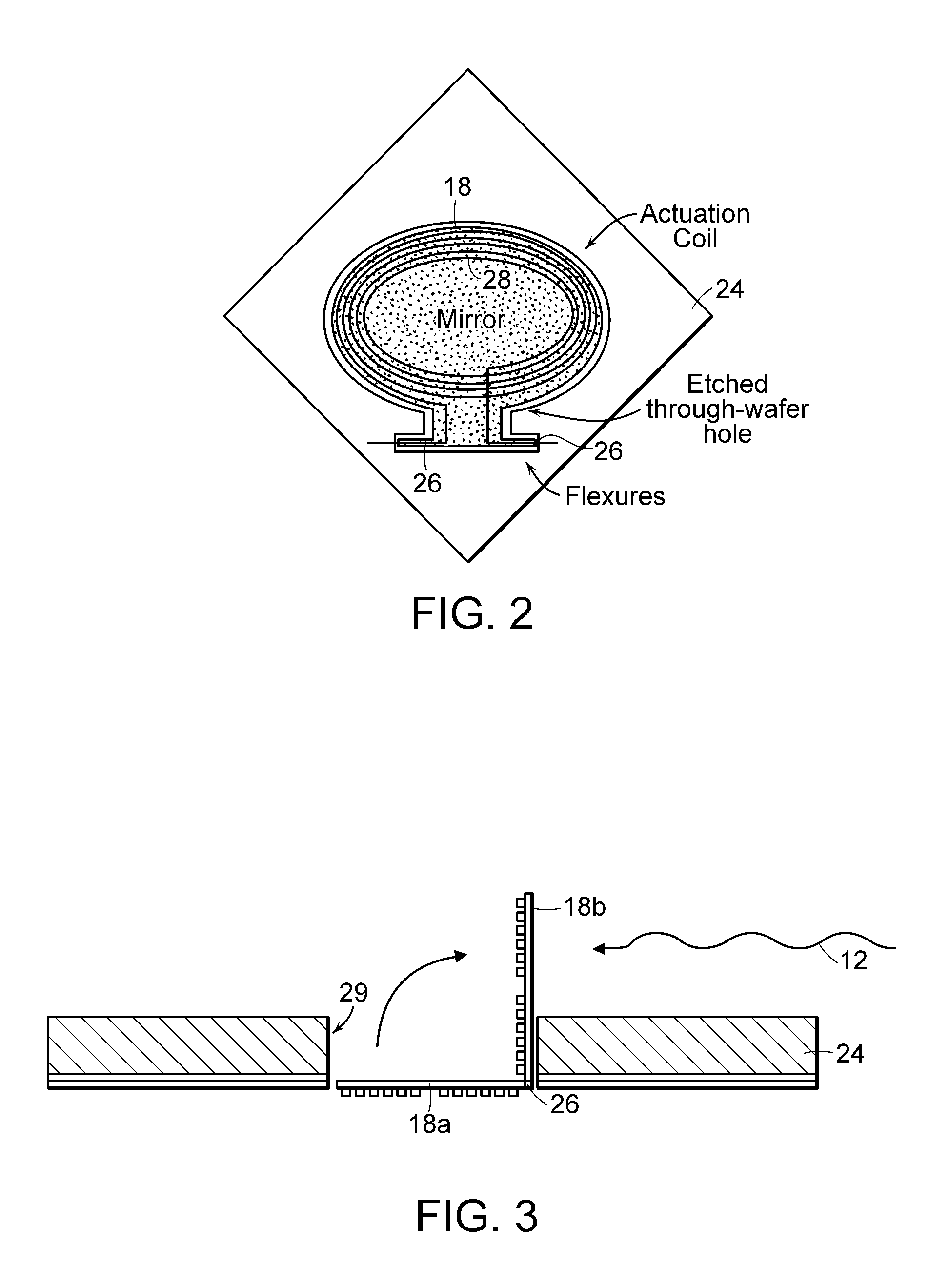
The invention provides a mechanism for latching movable mirrors in an optical switch without consuming power. The mechanism uses magnetic material on the mirrors and a structure proximate to the mirrors that are magnetized in the presence of magnetic flux from an array of magnets used in actuating the mirrors. The invention also provides two arrays of magnets located on opposite sides of the mirror array to enhance the magnetic field used in switching the mirrors. The technical effects of the invention include reducing the voltage needed to move the mirrors and improving the efficiency of the optical switch.

Problems solved by technology

One problem with prior art optical switches is that high voltages are needed for mirror actuation, which raises the cost of operating the switches.
Another problem with prior art switches is that they require continuous power to retain functionality.
Mirrors in the array that have been actuated from a rest position are not stable, i.e., they do not remain in an actuated state if power is removed from the switch.

Method used


Image

  • Latching mechanism for magnetically actuated micro-electro-mechanical devices
  • Latching mechanism for magnetically actuated micro-electro-mechanical devices
  • Latching mechanism for magnetically actuated micro-electro-mechanical devices

Examples


Embodiment Construction

[0009]In accordance with one embodiment of the invention, a latching mechanism is provided for latching movable mirrors in an optical switch. The mirrors are movable between rest and actuated positions, and the latching mechanism releasably secures mirrors in an actuated position without consuming power. The latching mechanism preferably includes magnetic material on each mirror and on a structure proximate the mirror. The magnetic materials are magnetized in the presence of magnetic flux from an array of magnets used in actuating the mirrors for latching the mirrors in their actuated state.

[0010]In accordance with another embodiment of the invention, two arrays of magnets are provided to enhance the magnetic field used in switching mirrors in the mirror array between rest and actuated positions. The two arrays of magnets are located on opposite sides of the mirror array. The stronger magnetic field reduces the voltage needed to move the mirrors.

[0011]These and other features of the...


PUM


Abstract

A latching mechanism is provided for selectively latching mirrors in an optical switch. The mirrors are selectively movable between rest and actuated positions. The latching mechanism provides stable latching of mirrors in an actuated position, i.e., without power being applied to maintain the actuated state.

Description

BACKGROUND OF THE INVENTION[0001]1. Field of the Invention[0002]The present invention relates generally to micro-electromechanical (MEMS) devices and, in particular, to arrayed magnetically actuated MEMS devices such as arrayed mirrors used in optical switches.[0003]2. Description of Related Art[0004]Optical switches are used for routing optical (i.e., light) signals in fiber optic networks. The switches are used to selectively transmit light signals from a set of input fibers to a set of output fibers. The switches typically include an array of movable mirrors or reflectors that can be selectively actuated to deflect light signals to particular output fibers.[0005]The mirror arrays are typically fabricated using MEMS manufacturing processes, which involve using silicon processing and related techniques common to the semiconductor industry to form micro-electromechanical devices.[0006]The movable mirrors can be actuated or controlled in a variety of ways including through electromag...

Claims


Application Information

Patent Timeline
Patent Type & Authority Patents(United States)
IPC IPC(8): G02B6/35
CPCG02B6/358G02B6/3518G02B6/3546G02B6/3572
Inventor BERNSTEIN, JONATHAN JAY
Owner CORNING INC
Learn More