
Electric actuator

a technology of electric actuators and actuators, applied in the direction of auxiliary welding devices, soldering apparatuses, gearing, etc., can solve the problems of significant maintenance and other costs, inability to fully realize the full range of limitations inherent in the worksite, and inability to fully realize the full range of limitations, so as to facilitate easy disassembly, replacement or repair of modular components, the effect of reducing maintenance costs

Inactive Publication Date: 2006-11-28
TOL O MATIC
View PDF55 Cites 31 Cited by
  • Summary
  • Abstract
  • Description
  • Claims
  • Application Information

AI Technical Summary

Benefits of technology

[0008]To minimize downtime and infra structure changes and the like during a changeover from existing fluid actuators to the electrically powered actuator of the present invention, the actuator of the present invention has been designed to fit within the same space or package and to be no heavier than existing fluid actuators, while at the same time providing at least comparable speed, thrust and range of movement. This is accomplished by utilizing a ball or roller screw electric actuator concept and by mounting the actuating motor in-line and directly to the actuator drive shaft. To provide additional advantages for maintenance or repair, the electric actuator of the present invention has also been designed to be comprised of a modular construction, thereby facilitating easy disassembly and substitution or repair of modular components.
[0010]The actuator of the present invention also includes a means and mechanism for manually overriding the electrically powered actuator in the event of a loss of electrical power, actuator jamming or other actuator malfunction and a mechanism for enabling the actuator head and / or end cap to be rotated or mounted in a variety of different positions and / or configurations to accommodate different welding, clamping or actuation environments. In a preferred embodiment, a lubrication assembly is provided for insuring sufficient actuator lubrication and thus a reduction in maintenance. Means are also provided for accommodating the various loads (such as side loads) which are common with the actuation for welding guns and the like.
[0012]Another object of the present invention is to provide an improved electrical actuator which can replace the conventional fluid actuators of the automotive manufacturing industry without sacrificing size or weight restrictions, while still maintaining comparable thrust, speed, range of movement and load accommodation.
[0014]Another object of the present invention is to provide an electric actuator that eliminates or minimizes impact loading as the thrust tube reaches its innermost travel position.

Problems solved by technology

While fluid actuators have functioned reasonably well for this purpose, they inherently embody various limitations.
One, because of the possibility of leaks and failure of seals, etc. in the fluid actuators, there is always the concern of contamination of the worksite by a leaking fluid.
Second, fluid actuators necessarily require a source of pressurized fluid and a fluid supply system.
This leads to significant maintenance and other costs.

Method used


Image

  • Electric actuator
  • Electric actuator
  • Electric actuator

Examples


Embodiment Construction

[0034]The present invention provides an improved actuator for use in providing controlled and accurate linear movement to a work piece. Although the actuator of the present invention has applicability to a variety of work pieces and in a variety of industries, it has particular application to the actuation of welding guns, clamping fixtures and the like for use in the automotive manufacturing industry. Accordingly, the preferred embodiment will be described with respect to the application of the present invention to welding guns, clamping fixtures or the like, without any implication that the present invention is limited to that application.

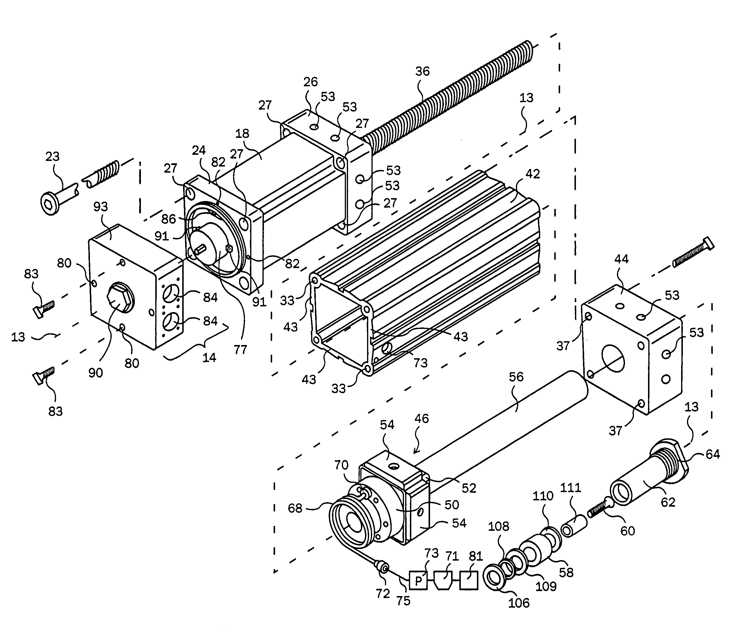
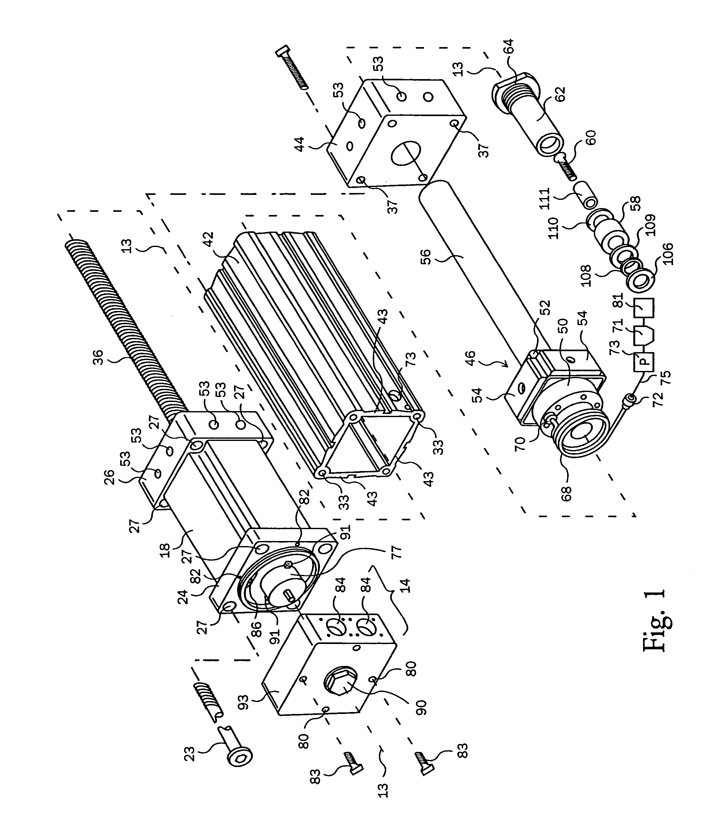
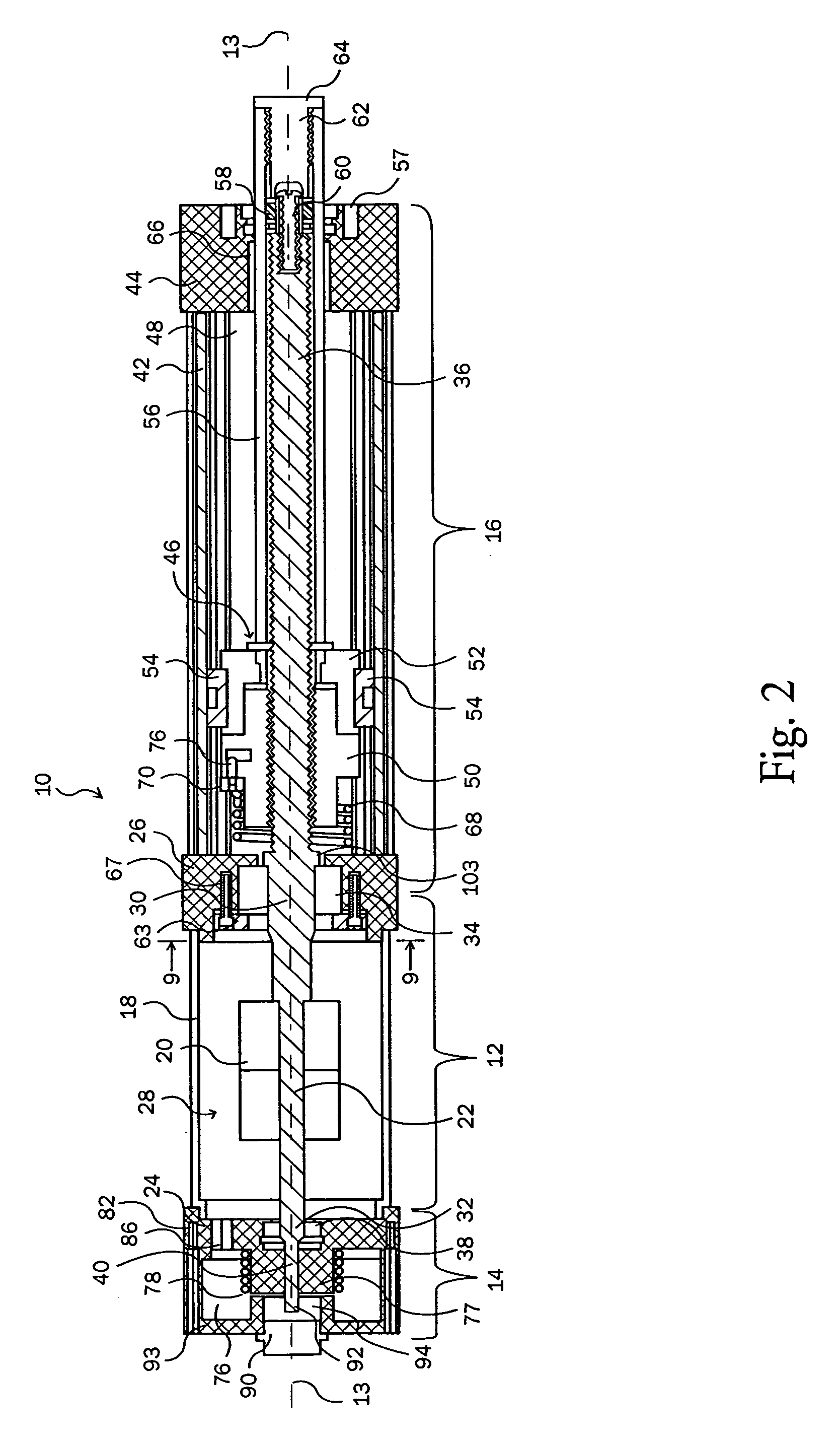
[0035]In describing the preferred embodiment of the present invention, reference is first made to FIGS. 1, 2 and 15 comprising exploded and sectional views of the actuator or portions thereof. In general, the actuator of the present invention is an electrically powered, in-line actuator in which the electric motor powering means is connected dire...


PUM

PropertyMeasurementUnit
angleaaaaaaaaaa
thrustaaaaaaaaaa
outer cross-sectional dimensionaaaaaaaaaa

Abstract

An electric actuator having an in-line rotation shaft, electric motor and encoder in which the encoder shaft, the motor shaft and the rotation shaft is concentric and integrally formed.

Description

CROSS-REFERENCE TO RELATED APPLICATION(S)[0001]This application claims the benefit of Provisional Application Ser. No. 60 / 264,330, filed Jan. 26, 2001.BACKGROUND OF THE INVENTION[0002]1. Field of the Art[0003]The present invention relates generally to an electrically powered linear actuator and more particularly to an electrically powered actuator having an inline, direct motor mount and adapted for a variety of robotic or other applications. The invention has particular application to the control of robotic, pedestal or fixture welding guns and specifically, welding guns utilized in the automotive industry. The invention also has application to the actuation of clamping fixtures and the like in various industries such as the automotive industry.[0004]2. The Prior Art[0005]Various industries, and particularly the manufacturing industry, have utilized linear actuators to control the movements of automated welding guns, automated clamping fixtures, and the like. Specifically, in the a...

Claims


Application Information

Patent Timeline
Patent Type & Authority Patents(United States)
IPC IPC(8): B23K37/02F15B13/00F16H25/20H02K7/06H02K11/00
CPCF16H25/20F16H57/0497H02K7/06H02K11/0015H02K11/0021F15B2013/006F16H25/2204F16H2025/2034Y10T74/18688F16H2025/2075Y10T74/18576F16H2025/2065H02K11/21H02K11/215
Inventor HOCHHALTER, KEITHCASE, EUGENE F.
Owner TOL O MATIC
Learn More