
Method of LED life extension and end-of-life prediction

a technology of led illumination and life extension, applied in the field of led illumination systems, can solve the problems of white leds that are expensive compared to monochromatic leds, white led illumination systems require a relatively high acquisition and implementation cost, and achieve the effects of prolonging the service life of led illumination sources, and reducing the cost of acquisition and implementation

Active Publication Date: 2006-11-21
LOCKHEED MARTIN CORP
View PDF10 Cites 27 Cited by
  • Summary
  • Abstract
  • Description
  • Claims
  • Application Information

AI Technical Summary

Benefits of technology

[0009]Accordingly, it is an object of the present invention to provide a new and improved method or technique for operating LED illumination systems so as to effectively extend the service life of the LED illumination sources, as well as to provide a new and improved method or technique for predicting the end of the service life of the LED illumination sources whereupon the LED illumination sources can be replaced at appropriate operational times.
[0011]An additional object of the present invention is to provide a new and improved method or technique for operating LED illumination systems which is effectively contrarian to conventional PRIOR ART methods or techniques of operating LED illumination systems whereby, in lieu of the LED illumination sources exhibiting relatively shortened service lives as a result of substantially rapidly deteriorating, degrading, or decaying illumination levels as a function of time, the LED illumination sources will exhibit relatively extended service lives.
[0012]A further object of the present invention is to provide a new and improved method or technique for predicting the end of the service life of the LED illumination sources whereupon the LED illumination sources can in fact be replaced at truly appropriate operational times so as not to be unnecesarily prematurely replaced, or alternatively, so as not to be inappropriately maintained in service whereby the imaging system can no longer in fact be used or wherein the imaging capabilities are unacceptably compromised.
[0013]A last object of the present invention is to provide a new and improved method or technique for operating LED illumination systems so as to effectively extend the service life of the LED illumination sources, as well as to provide a new and improved method or technique for predicting the end of the service life of the LED illumination sources whereupon the LED illumination sources can be replaced at appropriate operational times, all of which positively impact the economics concerning the implementation and operational maintenance of the imaging systems within which the LED illumination sources are being utilized.SUMMARY OF THE INVENTION

Problems solved by technology

On the other hand, white LEDs pose some operational challenges when viewed from an overall life-cycle perspective point of view.
More particularly, for example, white LEDs are expensive as compared to monochromatic LEDs, such as, for example, red LEDs.
As a result, a white LED illumination system requires a relatively high acquisition and implementation cost relative to conventional incandescent illumination systems.
Still yet further, white LEDs have an inherent operational characteristic of gradually losing their relative brightness levels during their service lives.
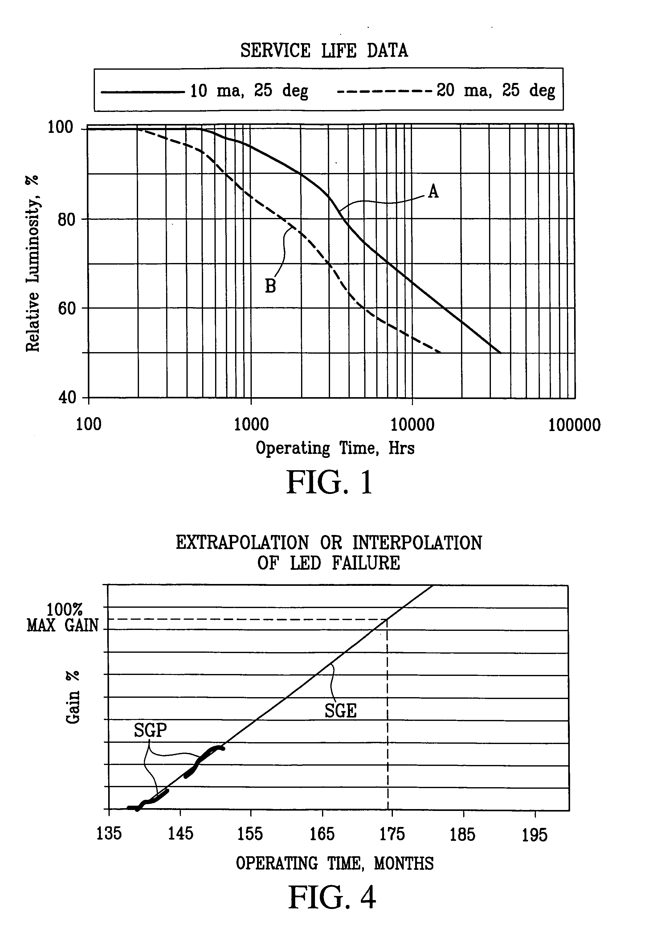
It has been discovered, however, that over a period of time, the clear plastic lens tends to yellow due to the light frequencies that are generated, and in turn, the yellowing of the plastic lens effectively tends to lower the light output from the white LEDs.
More particularly, there are several operational factors which not only lead to the aforenoted yellowing of the plastic lens, but in addition, such factors also affect the rate at which the plastic lens undergoes such a yellowing process.
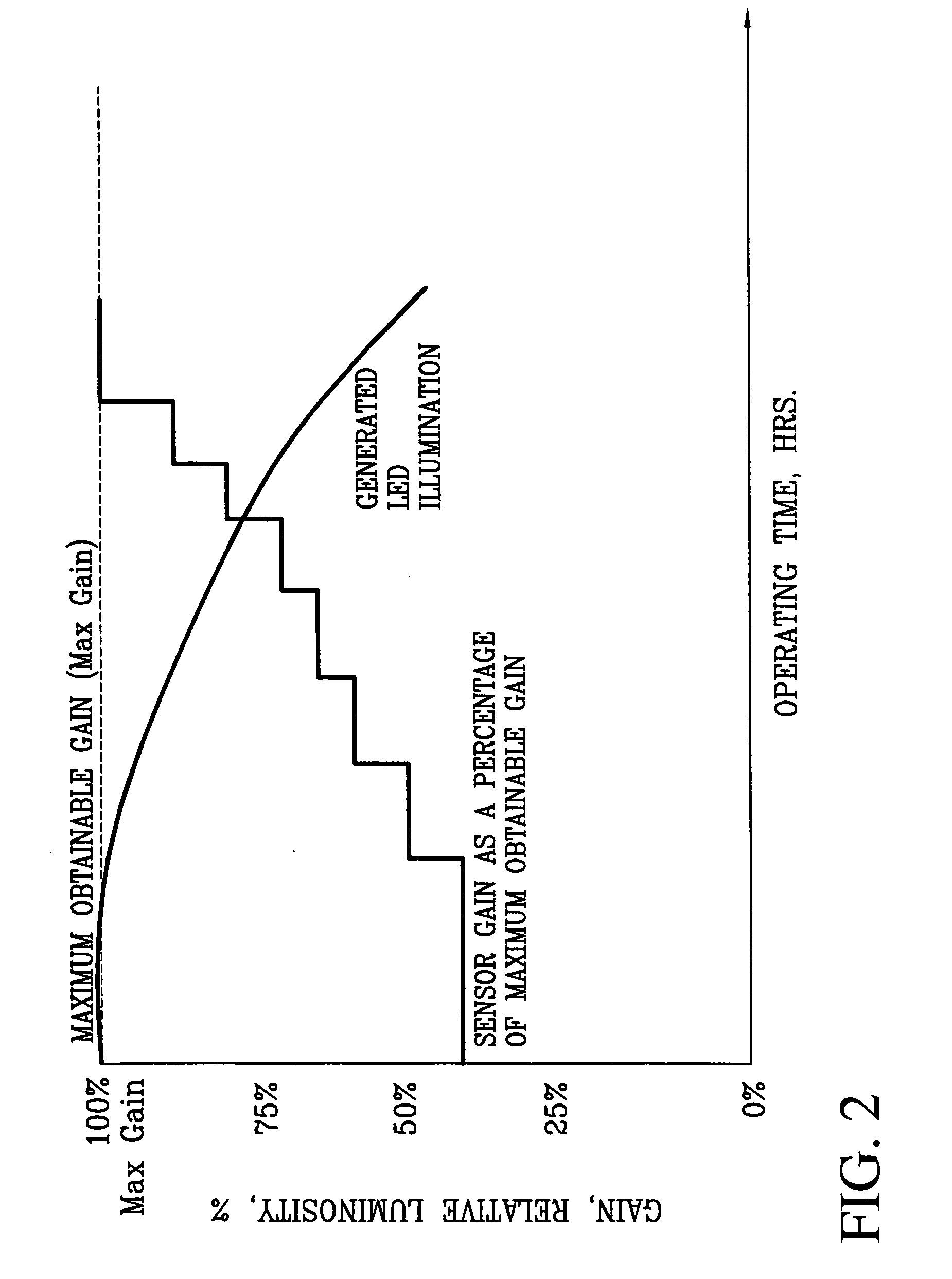
It is to be appreciated, however, that both the iris and gain control mechanisms have practical limits which, in reality, affect or limit the extents to which the exposure levels can in fact be affected.
For example, the iris control mechanism is limited by the size of the imaging system lens as well as the depth of field required by the system.
The gain control mechanism is effectively limited by the amount of noise that is acceptable to, or which can be tolerated by, the system.
Accordingly, there is a point or limit beyond which gain can no longer be increased due to the fact that the corresponding noise levels would be too high and therefore unacceptable with respect to the desired imaging capabilities or characteristics of the system.
During the time that such adjustments are being implemented, the image quality, as measured or determined by means of the depth of field and noise characteristics, will be adversely affected, and eventually, effective exposure compensation terminates when the real or practical limits of the depth of field or noise are exceeded.
It is of course readily appreciated from the graphical plot of FIG. 2 that eventually, viable gain adjustments can no longer be implemented in view of the fact that the gain level reaches 100% MAXIMUM OBTAINABLE GAIN, meaning, that if the gain signals are increased still further beyond such level, the resulting noise levels effectively impressed upon the resultant imaging scans would render the same unacceptable or undesirable.
Obviously, the economic impact of relatively high replacement costs, coupled with a foreshortened useful life expectancy effectively dictated by means of constantly deteriorating or degrading illumination levels, can have a substantial negative effect upon the implementation and operational costs of such a system over its entire service lifetime.

Method used


Image

  • Method of LED life extension and end-of-life prediction
  • Method of LED life extension and end-of-life prediction
  • Method of LED life extension and end-of-life prediction

Examples


Embodiment Construction

[0020]Referring now to the drawings, and more particularly to FIG. 3 thereof, there is illustrated a graphical plot of DUTY CYCLE and GAIN parameters, characteristic of, for example, a particular white LED being used as an illumination source within an imaging system, as a function of TIME, wherein such graphical plot is illustrative of the new and improved method or technique, developed in accordance with the principles and teachings of the present invention, for operating imaging system LED illumination sources in such a manner that the LED illumination sources will achieve and exhibit extended or enhanced service lives. More particularly, in lieu of, or contrary to, the conventional PRIOR ART practice of running or operating the LED illumination sources wherein the LED illumination sources are initially normally operated at their maximum output levels or in accordance with a one hundred percent (100%) duty cycle, and in conjunction therewith, wherein the sensor gain control is pr...


PUM


Abstract

A method or technique of operating the LED illumination system within a line scan camera comprises the operation of the LED illumination sources at a relatively high gain control level, less than the one hundred percent maximum or acceptable gain level, and a correspondingly reduced duty cycle level, which is less than one hundred percent (100%), so as to effectively reduce the aging of the LEDs and thereby achieve extended service lives for the LEDs. As the LEDs age with usage, whereby their luminosity levels degrade, the duty cycle percentage level is progressively increased until a maximum output or one hundred percent duty cycle percentage level is reached at which time the gain control percentage is progressively increased up until the maximum acceptable gain percentage level. An end-of-life prediction technique or routine is also capable of being derived from the progressively increased gain control percentages so as to enable the replacement of the LED illumination sources at appropriate times.

Description

FIELD OF THE INVENTION[0001]The present invention relates generally to light emitting diode (LED) illumination systems for use, for example, within line scan cameras, and more particularly to a new and improved method or technique for effectively extending the service life of LED illumination sources, as well as a related new and improved method or technique for predicting the end of the service life of the LED illumination sources whereupon the LED illumination sources will need to be replaced.BACKGROUND OF THE INVENTION[0002]With the advent of those particular light emitting diodes (LEDs) which generate bright-white light whereby such light emitting diodes (LEDs) can be used as viable and reliable illumination sources, many imaging systems, such as, for example, cameras, are replacing conventional incandescent illumination systems with LED-based illumination systems. The use of LEDs as a source of illumination for imaging systems has many operational advantages, as compared to con...

Claims


Application Information

Patent Timeline
IPC IPC(8): G09G3/32G09G3/30H05B37/03H05B44/00
CPCH05B33/0893H05B37/03H05B45/58H05B47/20
Inventor KROHN, ROBERT M.
Owner LOCKHEED MARTIN CORP
Learn More