
Bi-assembly spring end cap for vehicle on/off fan drive to improve seal life, reduce vibration input loading to ball bearings and reduce component cost

a technology of spring end cap and vehicle fan drive, which is applied in the direction of clutches, mechanical equipment, machines/engines, etc., can solve the problems of reducing efficiency, o-ring or seal damage to the friction clutch assembly, and not always desirable for such fan assemblies to run continuously. , to achieve the effect of reducing vibration and preventing corrosion

Active Publication Date: 2006-11-21
BORGWARNER INC
View PDF8 Cites 20 Cited by
  • Summary
  • Abstract
  • Description
  • Claims
  • Application Information

AI Technical Summary

Benefits of technology

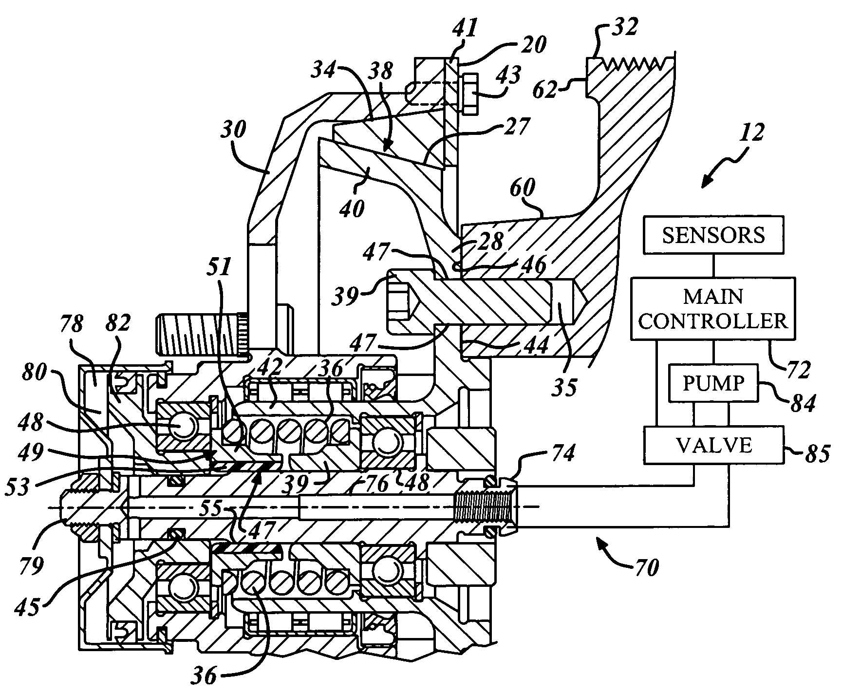
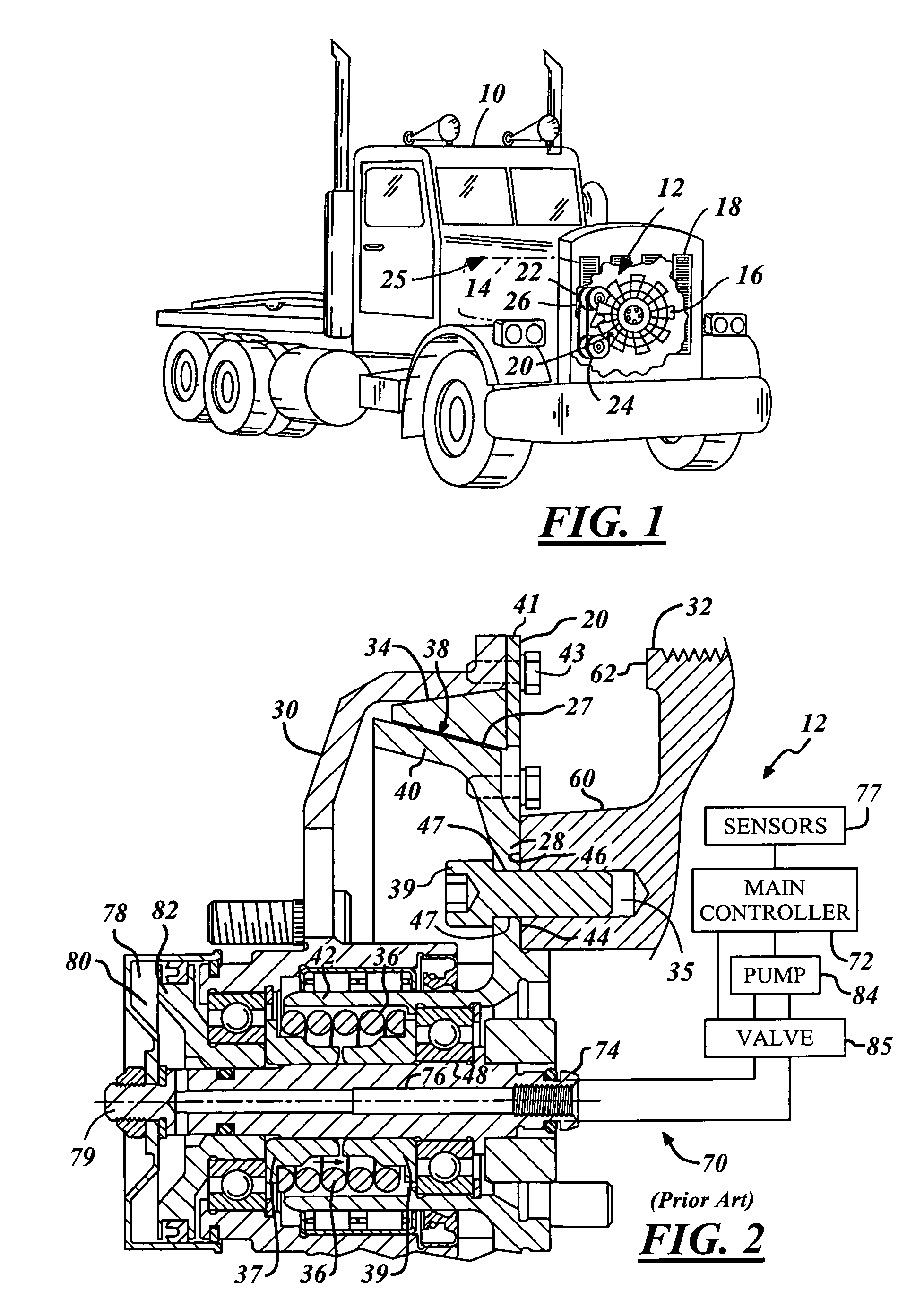
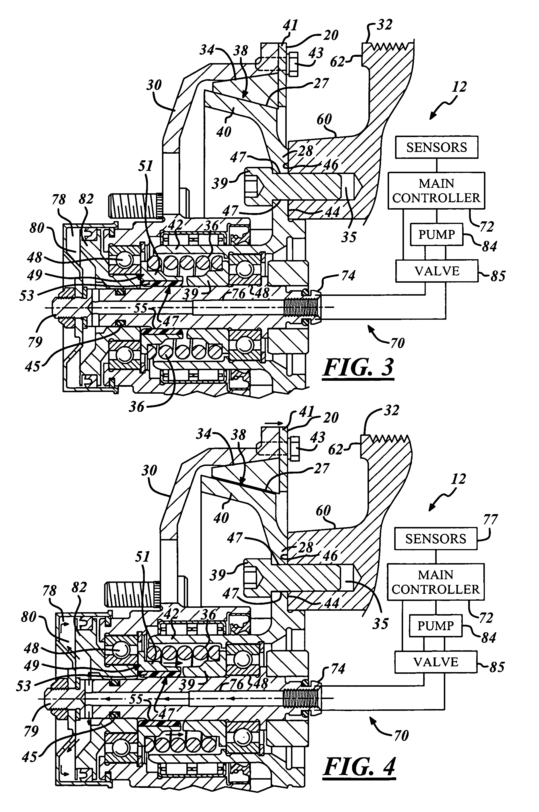
[0010]It is therefore an object of the present invention to provide a clutch assembly in which the steel end cap is insulated from the steel piston rod. The present invention provides for a non-metallic insulation that will prevent corrosion and act to reduce vibrations delivered to the front and rear ball bearings. Further, the non-metallic insulation will be molded, thus allowing for radii to be directly molded into the component.
[0011]The proposed invention, consisting of a multi-piece spring end cap eliminates the contamination, providing for a clean and debris free environment for extended seal and bearing life, while at the same time, dampening vibrations within the clutch assembly.

Problems solved by technology

It is not always desirable for such fan assemblies to run continuously.
Additionally, continuous operation when unnecessary places a non-required draw on the engine and thereby reduces efficiency.
There are several disadvantages of known dry friction drives.
One disadvantage is damage done to O-rings or seals within the friction clutch assembly.
It has been determined that one source of damage done to the O-rings is due to contamination introduced into the environment.
Another disadvantage is failure of the bearings within the friction clutch assembly.
Bearing failure has been linked with excessive vibrations to the assembly.
These problems stem from the interaction between components in known friction clutch assemblies.
Internal metal-to-metal contact between the piston rod and spring end cap, sets up the perfect environment for fretting corrosion when coupled with engine vibrations, thus producing significant amounts of oxide particles which contaminate and degrade a nearby seal.
Another problematic issue with known dry friction drives is the costly step of machining radii in the inner diameter of the steel spring end cap.

Method used


Image

  • Bi-assembly spring end cap for vehicle on/off fan drive to improve seal life, reduce vibration input loading to ball bearings and reduce component cost
  • Bi-assembly spring end cap for vehicle on/off fan drive to improve seal life, reduce vibration input loading to ball bearings and reduce component cost
  • Bi-assembly spring end cap for vehicle on/off fan drive to improve seal life, reduce vibration input loading to ball bearings and reduce component cost

Examples


Embodiment Construction

[0020]In the following figures the same reference numerals will be used to refer to the same components. While the present invention is described primarily with respect to a cone clutch fan drive system, the present invention may be adapted and applied to various systems including: hydraulic systems, electrical systems, pneudraulic systems, mechanical systems, pneumatic systems, vehicle systems, cooling systems, fan drive systems, friction drive systems, or other systems.

[0021]In the following description, various operating parameters and components are described for one constructed embodiment. These specific parameters and components are included as examples and are not meant to be limiting.

[0022]Also, in the following description various fan drive components and assemblies are described as an illustrative example. The fan drive components and assemblies may be modified depending upon the application. Although the following description addresses a specific type of control system th...


PUM


Abstract

An on / off clutch assembly is disclosed having a two component spring end cap. The spring end cap includes a steel cap portion and a non-metallic portion. The non-metallic portion extends along the entire length of the steel cap portion and is located between the steel cap portion and the piston rod. The new design insulates the steel piston rod from the steel spring end cap. This results in reduced corrosion of seals within the clutch assembly and contributes to improved conditions for bearings within the clutch assembly.

Description

TECHNICAL FIELD[0001]The present invention relates generally to a cone clutch fan drive and more particularly to a pneumatic cone clutch fan drive having a two-component spring end cap including a steel cap portion and a non-metallic portion.BACKGROUND OF THE INVENTION[0002]Vehicle engines commonly utilize cooling assemblies to remove excess heat from the engine and maintain an optimal operating temperature. The cooling assembly pumps a coolant through the engine and other components in order to control engine temperature. Heat generated within the engine and other components is absorbed by the coolant and dispersed into the surrounding atmosphere through the use of a radiator. In order to improve dispersal by the radiator, it is common to utilize fan assemblies to draw or force air past the radiator to assist in temperature transmission.[0003]It is not always desirable for such fan assemblies to run continuously. At times, it is desirable for the temperature within the coolant to i...

Claims


Application Information

Patent Timeline
IPC IPC(8): F01P7/02
CPCF01P7/085F16D25/082
Inventor SETTINERI, SAMUEL EDGAR
Owner BORGWARNER INC
Learn More