
Actuator

a technology of actuators and actuators, applied in the field of actuators, can solve the problems of high development cost of piezoactuators, inability to be used for applications, and large displacements that cannot be extracted

Active Publication Date: 2006-11-21
ASAHI ENTERPRISE +2
View PDF3 Cites 2 Cited by
  • Summary
  • Abstract
  • Description
  • Claims
  • Application Information

AI Technical Summary

Benefits of technology

"The present invention provides an actuator that allows for ultrafine positioning, with small hysteresis and a low development cost. The actuator uses a diaphragm and a pressure plate to create a balance of pressures that act on the rod, resulting in a small temperature drift and low noise. The actuator can maintain high precision even in an open loop and can be used in applications that do not require mass production or low cost. The actuator uses a nozzle and a cover body to detect displacement due to pressure, and plural notches can be used to cancel out displacement in a certain direction. Overall, the actuator provides precise positioning and is easy to use in various applications."

Problems solved by technology

In a prior art piezoactuator, since there is a large amount of hysteresis, closed loop control must be performed.
Also, since the piezoactuator has a high development cost, it is limited to applications which assume mass production or applications where high cost can be tolerated, and it cannot be used for applications which do not assume mass production or low-cost applications.
Moreover, with a piezoactuator, if the applied voltage is not increased, a large displacement amount cannot be extracted.
On the other hand, in the case of a bellows actuator, since the distortion amount determines the displacement amount, temperature drift increases.
Also, it is easily affected by external noise, closed loop control is indispensable for increasing precision, and it is difficult to manufacture it at low cost.

Method used


Image

  • Actuator
  • Actuator
  • Actuator

Examples


Embodiment Construction

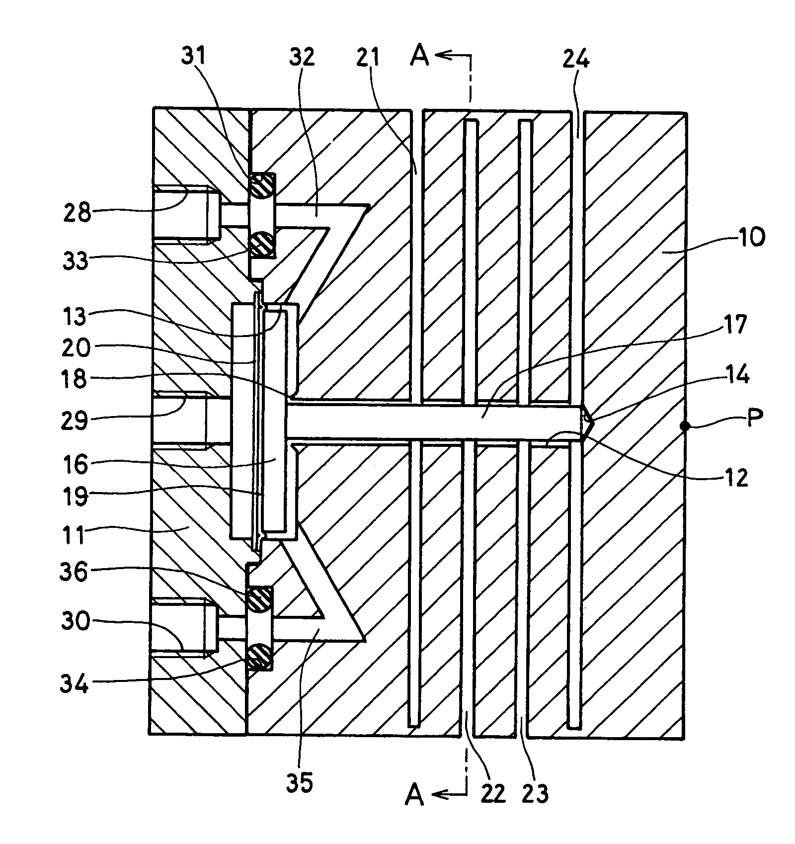
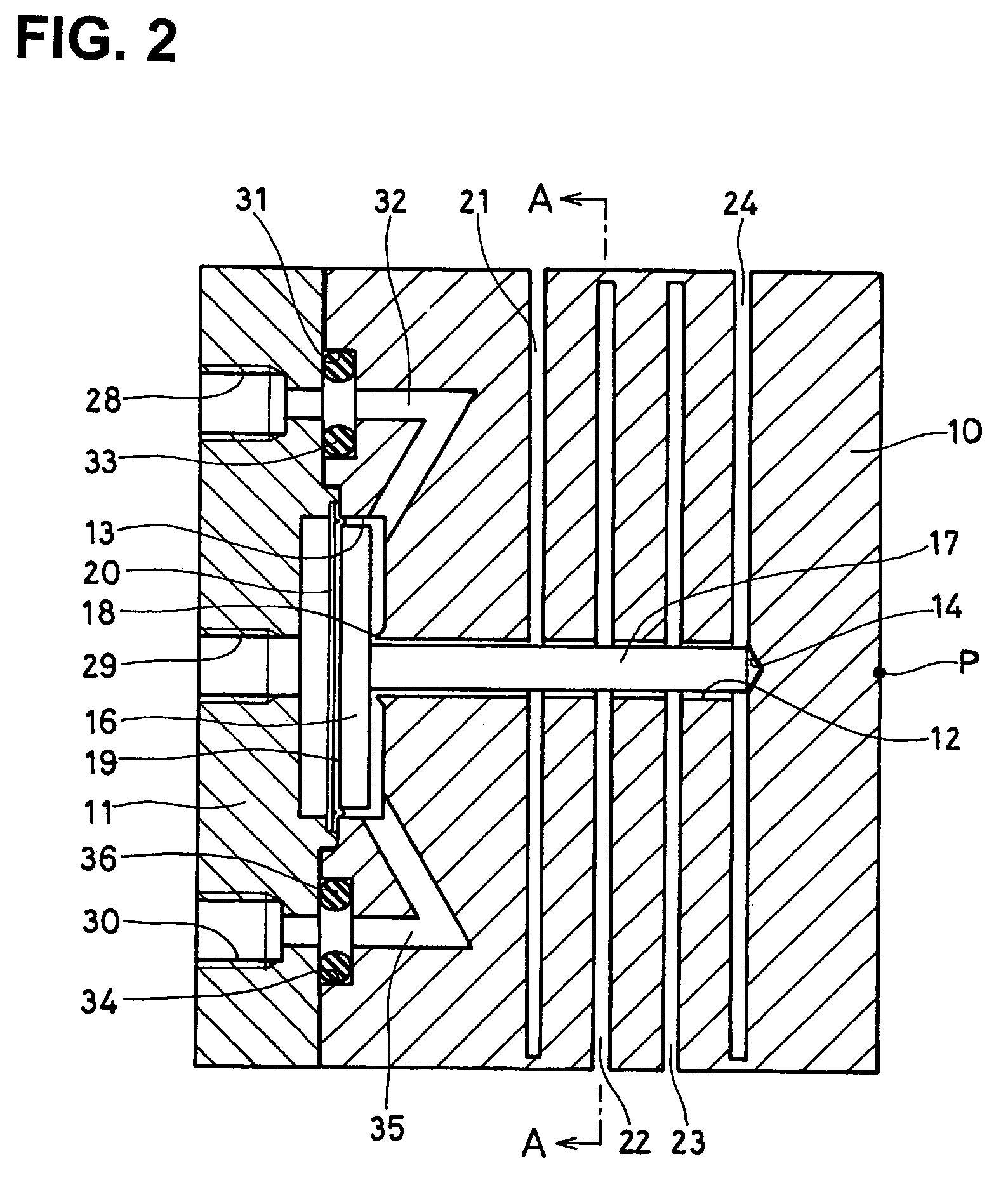
[0030]An embodiment of the invention will now be described referring to the drawings. FIG. 1 to FIG. 4 show an actuator according to this embodiment, the actuator comprising a body 10 having an essentially cubic shape as shown in FIG. 1. The body 10 may be made of for example stainless steel, carbon steel or aluminium alloy. As shown in FIG. 2, a cover body 11 likewise of stainless steel or carbon steel is attached to one end side of the body 10. As shown in FIG. 2, a throughhole 12 passes through the center part of the body 10 in a horizontal direction. A circular depression 13 is formed in a base end part of the throughhole 12. This depression 13 is open at one end of the body 10. On the other hand, the tip part of the throughhole 12 forms a contact abutting part 14.

[0031]Within the circular depression 13, a pressure plate 16 which is a circular plate one order of magnitude smaller than this circular depression 13, is disposed. A rod 17 is installed in this pressure plate 16 so th...


PUM


Abstract

An actuator is provided to generate an ultrafine stroke according to a fluid input pressure such as air pressure or the like. A throughhole 12 is formed in a center part of a body 10 so as to traverse a body 10 having plural notches 21–24 formed vertically on the body, a depression 13 is formed at the end of the body 10, and a rod 17 connected with a pressure plate 16 housed and held in the depression 13 is disposed in this throughhole 20. When an input pressure is applied to the pressure plate 16 via a diaphragm 19, an output point P generates a stroke due to the elastic deformation of a join part at the end of the notches 21–24.

Description

BACKGROUND OF THE INVENTION AND RELATED ART STATEMENT[0001]This invention relates to an actuator, in particular an actuator to which a pressure is input and a displacement according to the input pressure is extracted.[0002]A piezo actuator or bellows actuator has been proposed as a nanoactuator in which ultrahigh precision positioning is possible so that a minute, high precision displacement can be extracted.[0003]A piezo actuator is a piezoelectric element which is polarized in a predetermined direction, and extracts a displacement using a distortion deformation by applying a voltage to this piezoelectric element. On the other hand, a bellows actuator is an actuator wherein positional control is performed by feedback of a force applied to a bellows and a distortion amount of the bellows due to this force.[0004]In a prior art piezoactuator, since there is a large amount of hysteresis, closed loop control must be performed. Also, since the piezoactuator has a high development cost, i...

Claims


Application Information

Patent Timeline
Patent Type & Authority Patents(United States)
IPC IPC(8): F01B19/00
CPCF15B15/1428F15B15/1476
Inventor IIZUKA, HIROMICHI
Owner ASAHI ENTERPRISE
Learn More