
Parallel printing architecture using image marking engine modules

a printing architecture and image marking technology, applied in the direction of instruments, electrographic process equipment, optics, etc., can solve the problems of low reliability of sheet conveyance, time for refeeding of sheets, and reduced efficiency

Active Publication Date: 2006-11-14
XEROX CORP
View PDF68 Cites 68 Cited by
  • Summary
  • Abstract
  • Description
  • Claims
  • Application Information

AI Technical Summary

Benefits of technology

The system enables high-speed, efficient, and cost-effective printing with improved productivity by allowing single pass duplexing and multi-pass printing, reducing image misregistration and operational complexity while maintaining system redundancy.

Problems solved by technology

However, this system is efficient when many sheets having a record of the same content are to be prepared, but is very inefficient when many sheets having different records on both surfaces thereof are to be prepared.
To avoid this, recording may be effected on each sheet in such a manner that the front and back surfaces of each sheet provide the front and back pages, respectively, but this takes time for the refeeding of sheets and the efficiency is reduced.
Also, in the prior art methods, the conveyance route of sheets has been complicated and further, the conveyance route has unavoidably involved the step of reversing sheets, and this has led to extremely low reliability of sheet conveyance.
This system requires an increase in time and labor.
Where two types of information are to be recorded on one surface of the same sheet in superposed relationship, sufficient care must be taken of the image position accuracy, otherwise the resultant copy may become very unsightly due to image misregistration or deviation from a predetermined image recording frame.
However, the respective systems have their own speed limits and if an attempt is made to provide higher speeds, numerous problems will occur and / or larger and more bulky apparatuses must be used to meet the higher speed demands.
The larger and bulkier apparatuses, i.e. high speed printers, typically represent a very expensive and uneconomical apparatus.
The expense of these apparatuses along with their inherent complexity can only be justified by the small percentage of extremely high volume printing customers.

Method used


Image

  • Parallel printing architecture using image marking engine modules
  • Parallel printing architecture using image marking engine modules
  • Parallel printing architecture using image marking engine modules

Examples


Embodiment Construction

[0024]While the present printing apparatus and method will hereinafter be described in connection with exemplary embodiments, it will be understood that it is not intended to limit the embodiments. On the contrary, it is intended to cover all alternatives, modifications and equivalents as may be included within the spirit and scope of the embodiments as defined by the appended claims.

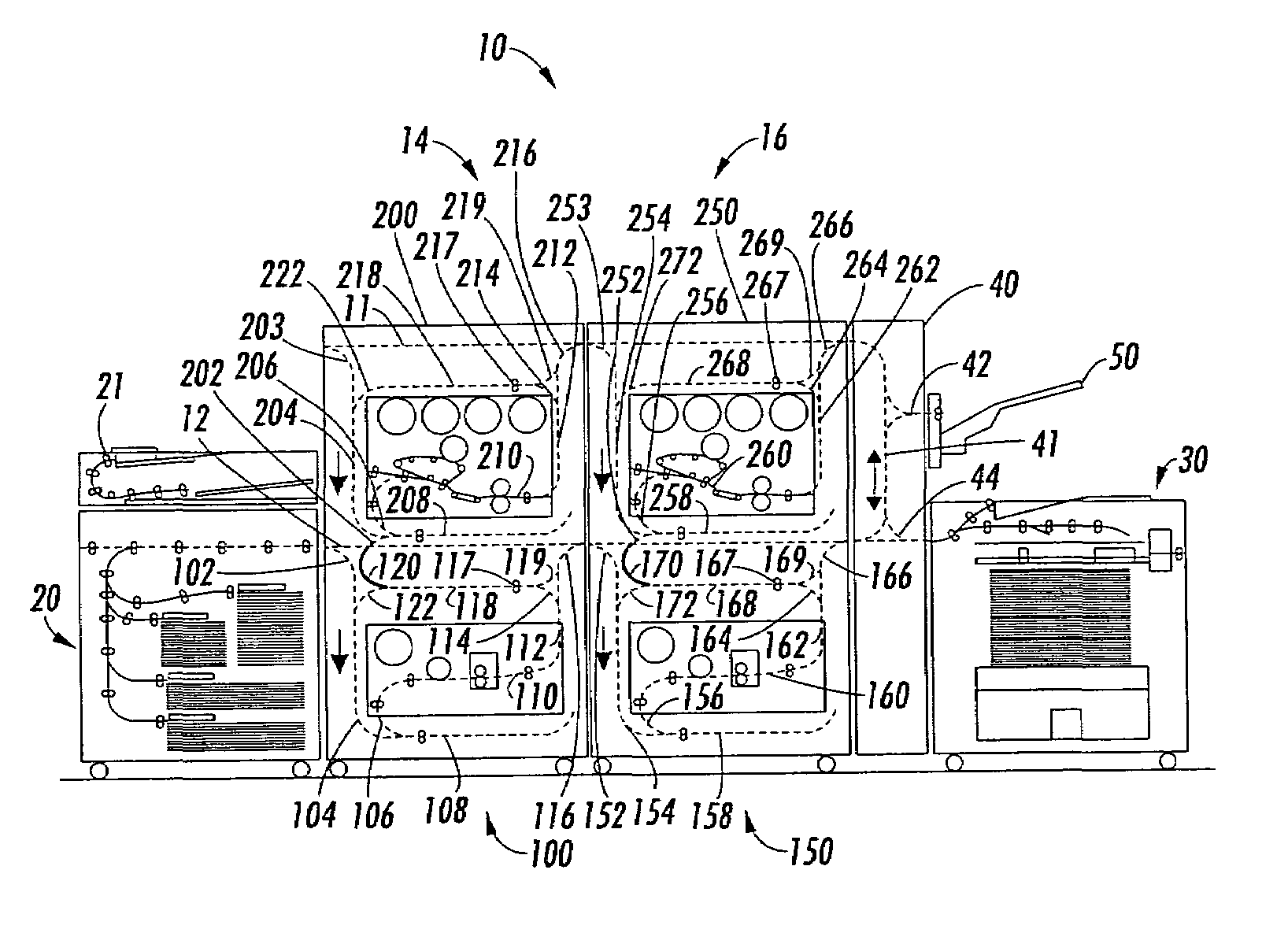
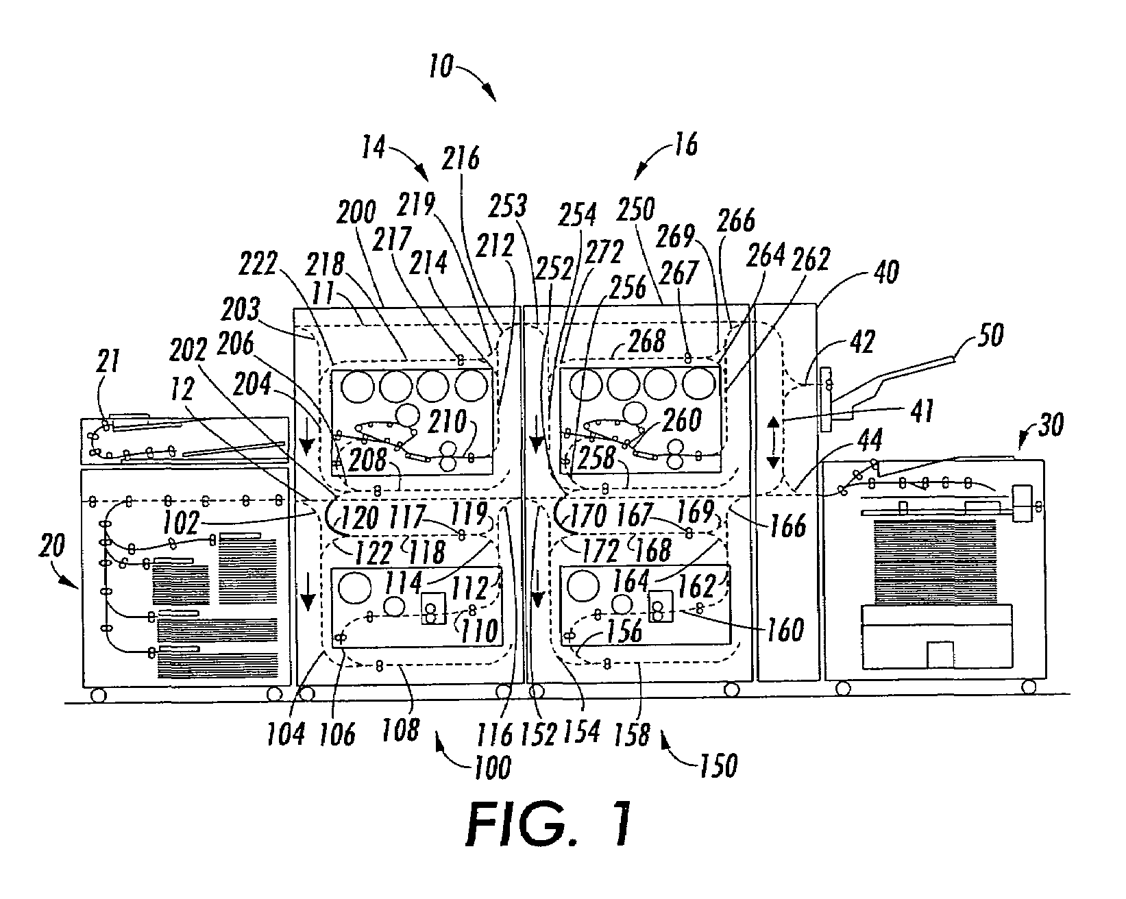
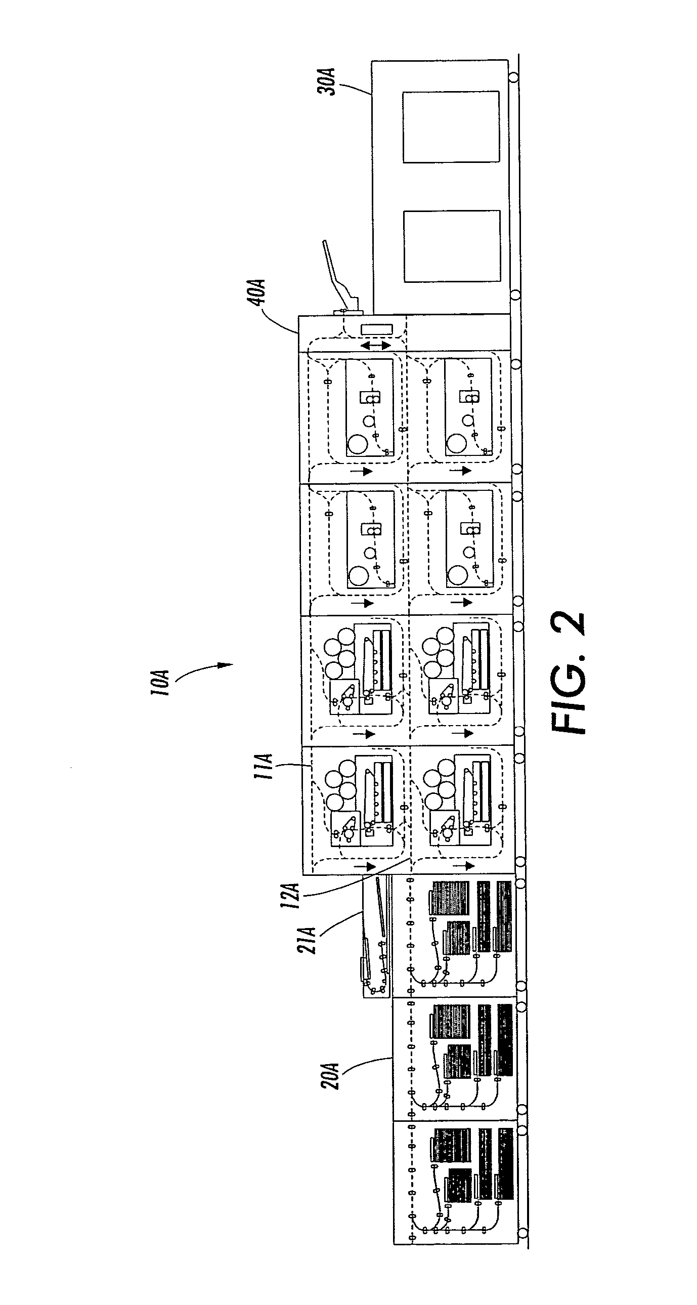
[0025]The embodiments, to be described below, consist of a plurality of Image Marking Engines (IME). The IMEs can be, for example, any type of ink-jet printer, a electrophotographic printer, a thermal head printer that is used in conjunction with heat sensitive paper, or any other apparatus used to mark an image on a substrate. The IMEs can be, for example, black only (monochrome) and / or color printers. Examples of different varieties of black and color printers are shown in the FIGS. 1–6, but other varieties, types, alternatives, quantities, and combinations can be used within the scope of the exemplar...


PUM


Abstract

An integrated printing system is provided and includes at least two generally vertically aligned image marking engines and at least two generally horizontally aligned image marking engines. The printing system further includes at least one generally horizontal interface media transport for transporting media between and to the vertically aligned and the horizontally aligned image marking engines.

Description

BACKGROUND[0001]U.S. patent application Ser. No. 10 / 917,768, filed Aug. 13, 2004; U.S. patent application Ser. No. 10 / 924,106, filed Aug. 23, 2004; U.S. patent application Ser. No. 10 / 924,113, filed Aug. 23, 2004; and U.S. patent application Ser. No. 10 / 924,458, filed Aug. 23, 2004.[0002]There is disclosed herein in embodiments a plurality of image marking engines or image recording apparatuses providing a multifunctional and expandable printing system. It finds particular application in conjunction with integrated printing modules consisting of several marking engines, each having the same or different printing capabilities, and will be described with particular reference thereto. However, it is to be appreciated that the illustrations of embodiments herein are also amenable to other like applications.[0003]Various apparatuses, i.e. xerographic imaging system, for recording images on sheets have heretofore been put into practical use. For example, there are copying apparatuses of t...

Claims


Application Information

Patent Timeline
Patent Type & Authority Patents(United States)
IPC IPC(8): G03G15/00
CPCG03G15/238G03G15/6529G03G2215/00021
Inventor MANDEL, BARRY PAULMOORE, STEVEN R.LOFTHUS, ROBERT M.DEJONG, JOANNES N. M.WILLIAMS, LLOYD A.KRUCINSKI, MARTINQUESNEL, LISBETH S.
Owner XEROX CORP
Learn More