
Surface-placed sound capturing microphone with rotatable cable connecting member

a technology of rotatable cables and microphones, applied in the direction of piezoelectric/electrostrictive transducers, microphone structural associations, transducer types, etc., can solve the problems of major problems such as the spoiled beauty of the cable portion, etc., and achieve the effect of enhancing the electric shielding function of the microphon

Active Publication Date: 2006-11-14
AUDIO-TECHNICA
View PDF8 Cites 6 Cited by
  • Summary
  • Abstract
  • Description
  • Claims
  • Application Information

AI Technical Summary

Benefits of technology

The solution allows for flexible cable positioning without compromising the microphone's aesthetic appeal or functionality, enhancing electrical shielding and reducing the risk of cable damage, while maintaining reliable connectivity.

Problems solved by technology

However, the surface-placed sound capturing microphone has a major problem to be solved.
Therefore, since one part of the output cable is exposed to the table surface at any time, the extracted portion of the cable spoils the beauty.
When a number of the microphones are used on a table in a TV studio, the beauty is further spoiled.
However this reconstruction needs to use tools for processing the microphone case and needs time or skill and further causes failure of the microphone.

Method used


Image

  • Surface-placed sound capturing microphone with rotatable cable connecting member
  • Surface-placed sound capturing microphone with rotatable cable connecting member
  • Surface-placed sound capturing microphone with rotatable cable connecting member

Examples


Embodiment Construction

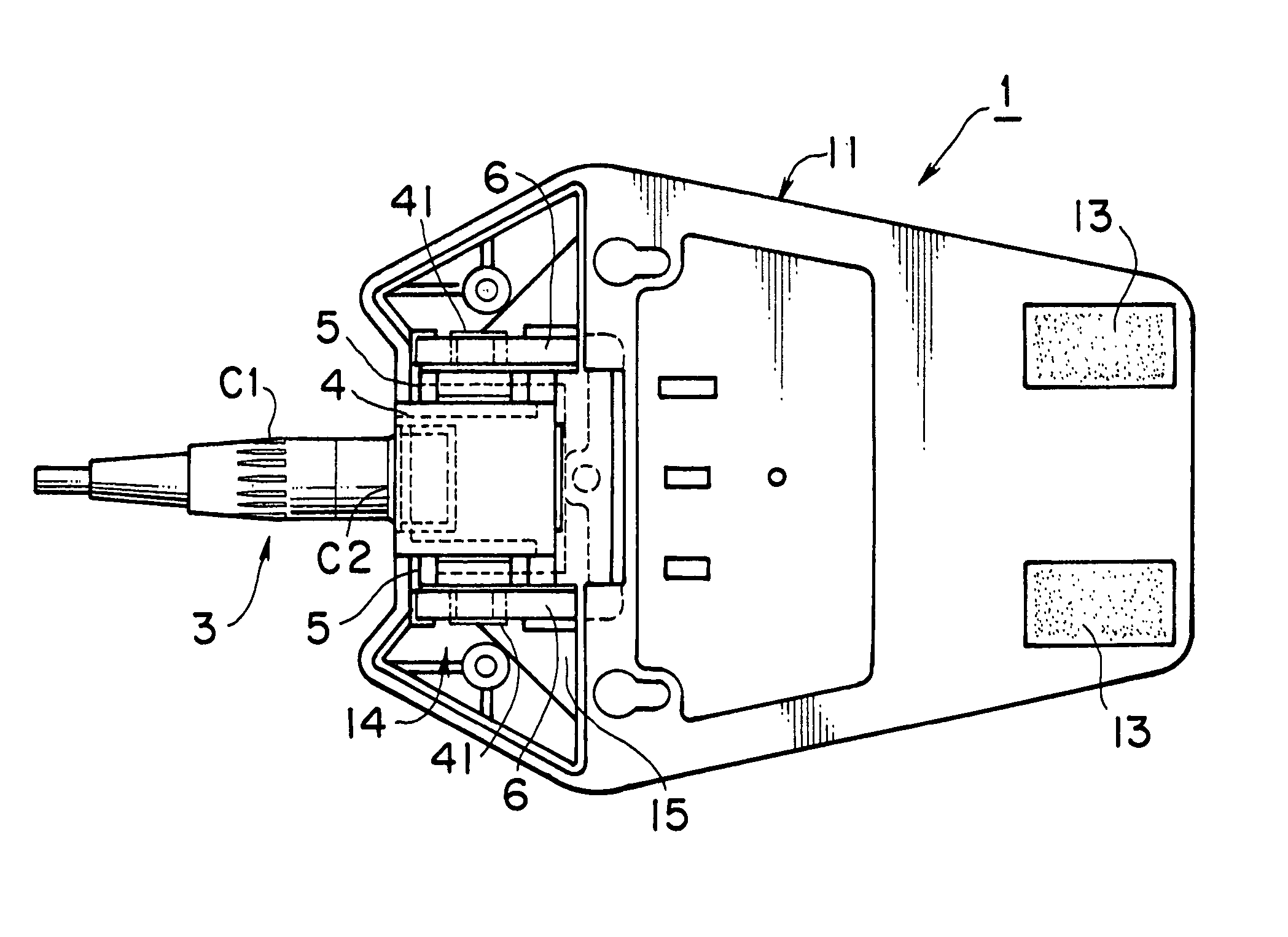
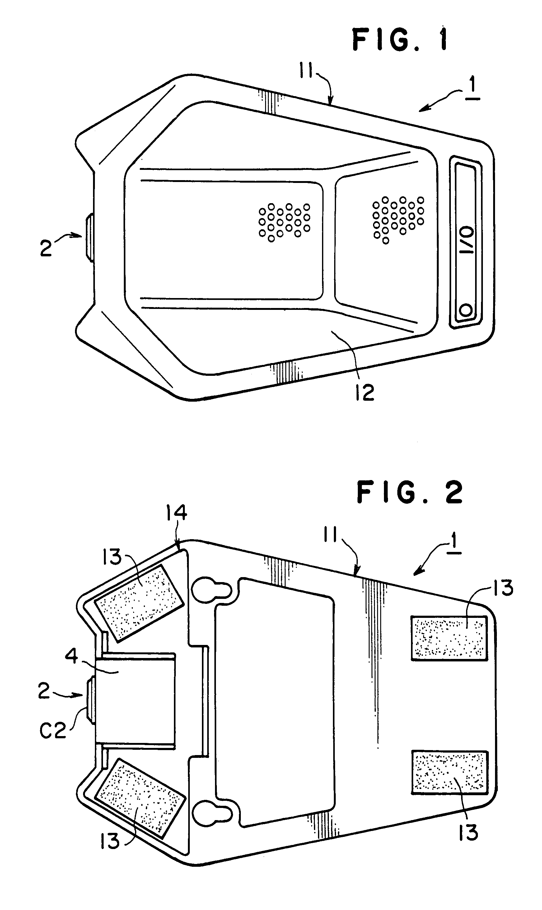
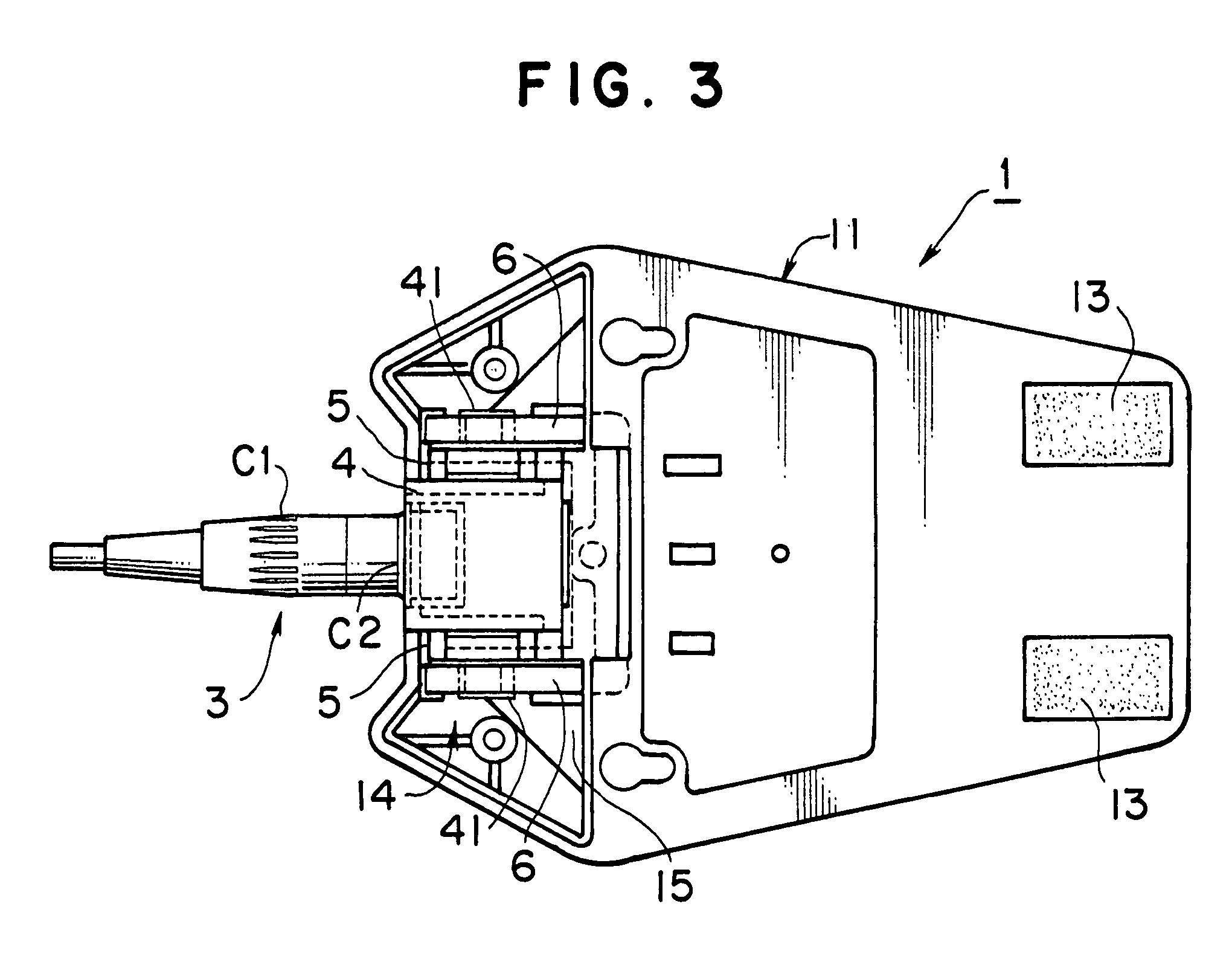
[0026]Referring to drawings, an embodiment of this invention will be described. FIGS. 1 and 2 are, respectively, a plan and a bottom plan views of a surface-placed sound capturing microphone with a rotatable cable connecting member embodying the present invention. FIG. 3 is a rear plan view of the microphone embodying the invention, as seen with a bottom panel removed.

[0027]The microphone 1 includes a low profile microphone case 11 which is placed in parallel to a horizontal surface such as a table. The microphone case has a microphone capsule therein which is a capacitor microphone or the like. A cover 12 having a number of through holes communicating with the microphone capsule is mounted on the upper side (the obverse side of FIG. 1 relating to the page space) of the microphone case 11.

[0028]The bottom side of the microphone case 11 has an anti-slip member for preventing the case from slipping and a foot member 13 for absorbing a vibration when the case is placed on the surface. ...


PUM


Abstract

The subject invention provides a surface-placed a surface sound capturing microphone with a rotatable cable connecting member to allow the output cable extracted position to be simply changed. A surface-placed sound capturing microphone of the subject invention includes a connecting member 2 which connects one end of an output cable 3 for transferring an audio signal captured by a microphone capsule to a predetermined external instrument. The connecting member 2 is mounted in the microphone case 11 and is rotatable around a horizontal rotating shaft in parallel to the placed surface. The output cable of the microphone can be positioned at a horizontal extracted position where the cable is horizontally extracted in parallel to the placed surface and at a vertical extracted position where the cable is vertically extracted relating to the placed surface.

Description

FIELD OF THE INVENTION[0001]The present invention relates to a surface-placed sound capturing microphone including a low profile microphone case placed on a horizontal surface such as a table. The invention especially relates to the surface-placed sound capturing microphone with an extracted direction of an output cable connected to the microphone changing.BACKGROUND OF THE INVENTION[0002]One of desk-top microphones which are used on a table in a conference room or a TV studio is a surface-placed sound capturing microphone. As shown in Japanese Utility Model Registration No. 2515812, the surface-placed sound capturing microphone is called a boundary microphone or a surface-mounted microphone. A low profile microphone case of the microphone is placed on a plane surface such as a table.[0003]The height of a microphone case of the microphone of this kind is low so that the microphone is indistinct and good-looking on TV compared with other desk-top microphones, even if the microphone i...

Claims


Application Information

Patent Timeline
Patent Type & Authority Patents(United States)
IPC IPC(8): H04R25/00H04R1/00H04M1/00H04R1/04H04R1/06H04R1/28H04R11/04H04R21/02
CPCH04R1/2892H04R2499/11
Inventor KONDO, KAZUHISA
Owner AUDIO-TECHNICA
Learn More