
Apparatus for feed contacting with immediate catalyst separation

a technology of catalyst separation and feed contact, which is applied in the direction of lighting and heating apparatus, furnace types, furnaces, etc., to achieve the effect of limiting the contact tim

Inactive Publication Date: 2006-11-14
UOP LLC
View PDF17 Cites 16 Cited by
  • Summary
  • Abstract
  • Description
  • Claims
  • Application Information

AI Technical Summary

Benefits of technology

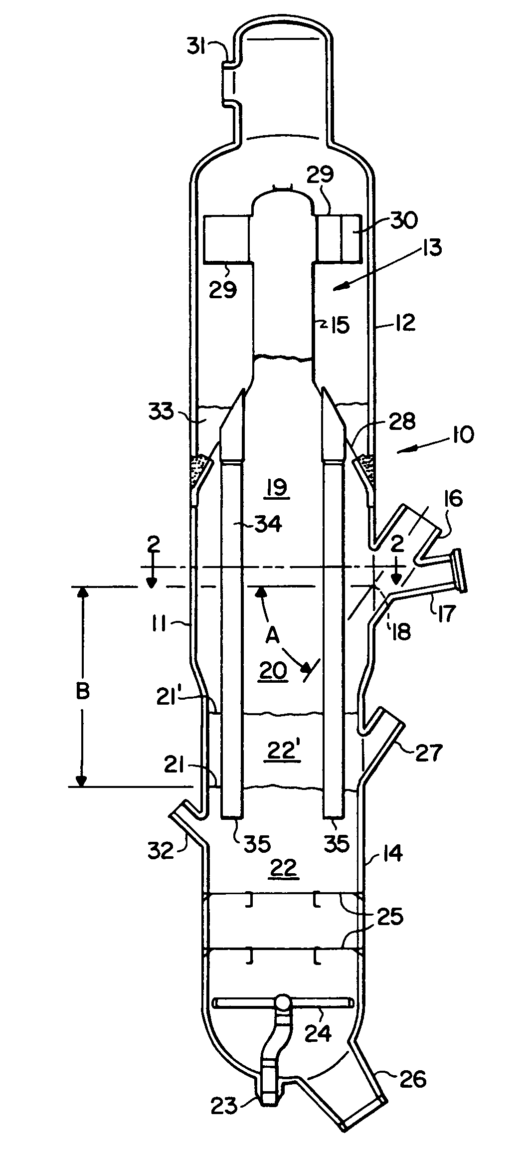
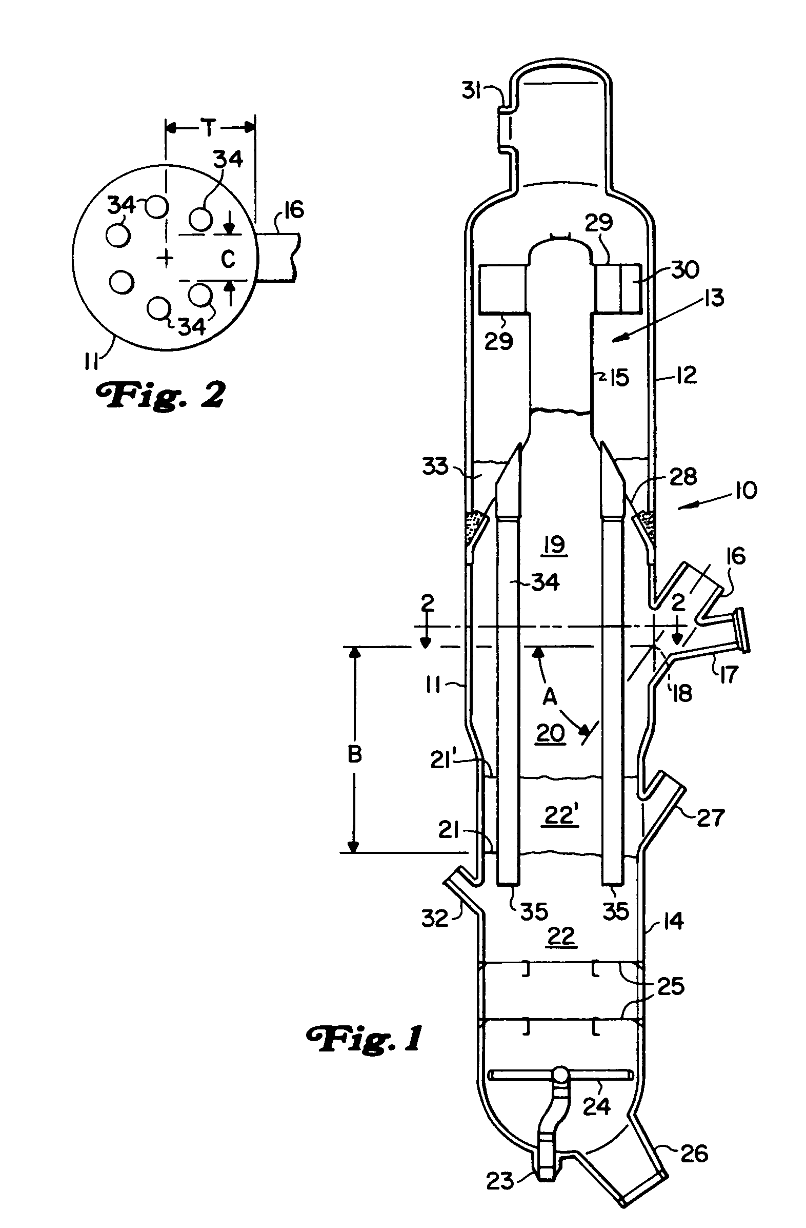
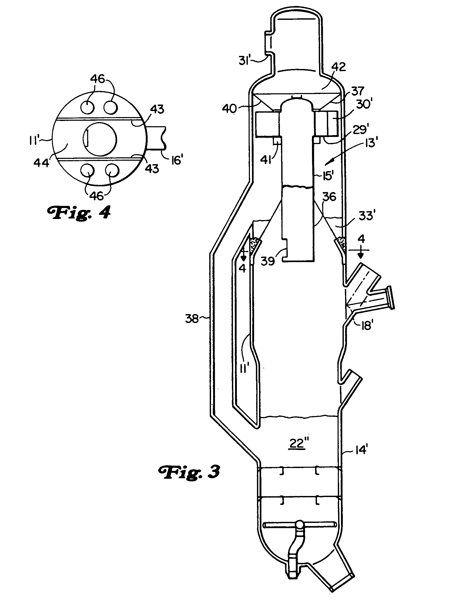
[0010]An object of this invention is to further limit contact time between catalyst and hydrocarbon in an arrangement for contacting relatively heavy hydrocarbon feeds and fluidized catalyst particles for ultra short periods of time.
[0013]Typically, a jet of a hydrocarbon-containing feed is injected—in a principally transverse direction—into a flowing layer of catalyst particles upstream of the injection point and at the periphery of the disengaging zone or outside of the disengaging zone. A particularly useful form of this invention uses a standpipe as a location for a distributor nozzle arrangement that performs contacting of a hydrocarbon-containing stream with a falling layer of particulate material. Generally the injection of the jet of hydrocarbon-containing feed into the flowing layer of catalyst particles takes place in the confined conduit, but near the outlet of the conduit into the disengaging vessel. Location of the distributor in standpipe will typically allow the discharge of the fluid and solids mixture directly from the distributor into the disengaging vessel at a suitable elevation for the practice of this invention. A standpipe distributor arrangement can fit compactly near the junction of most standpipes with the disengaging vessel.

Problems solved by technology

The processing of increasingly heavier feeds in FCC type processes and the tendency of such feeds to elevate coke production and yield undesirable products has led to new methods of contacting feeds with catalyst.

Method used


Image

  • Apparatus for feed contacting with immediate catalyst separation
  • Apparatus for feed contacting with immediate catalyst separation
  • Apparatus for feed contacting with immediate catalyst separation

Examples


Embodiment Construction

[0023]This invention can be used in combination with any type of particulate material. The material may be inert or reactive in the presence of the particular fluid material. A wide variety of inert and catalytic material is suitable for this invention. For example in destructive distillation processes a suitable inert material comprises an alpha alumna. FCC applications of this process can include any of the well-known catalysts that are used in the art of fluidized catalytic cracking. These compositions include amorphous-clay type catalysts which have, for the most part, been replaced by high activity, crystalline alumna silica or zeolite-containing catalysts. Zeolite-containing catalysts are preferred over amorphous-type catalysts because of their higher intrinsic activity and their higher resistance to the deactivating effects of high temperature exposure to steam and exposure to the metals contained in most feedstocks. Zeolites are the most commonly used crystalline alumna sili...


PUM

PropertyMeasurementUnit
timeaaaaaaaaaa
distanceaaaaaaaaaa
boiling pointaaaaaaaaaa

Abstract

A particular arrangement of an FCC unit creates an immediate and sustained gravity separation of catalyst and hydrocarbon vapors in short contact time cracking operation. A transverse feed contactor ejects the mixture of catalyst and hydrocarbon vapors transversely into a central portion of a separation vessel for vertical disengagement of catalyst from vapors. The vapors travel upwardly in the vessel into an inertial separator that quickly segregates entrained catalyst from the hydrocarbon vapors and collects separated catalyst at a higher elevation for stripping of adsorbed hydrocarbons from the catalyst.

Description

CROSS-REFERENCE TO RELATED APPLICATIONS[0001]This application is a Divisional application of Ser. No. 09 / 270,585 filed Mar. 16, 1999, now U.S. Pat. No. 6,063,263, which application claims the benefit of the filing date of Provisional Application Ser. No. 60 / 082,965 filed Apr. 24, 1998, the contents of which are hereby incorporated by reference.BACKGROUND OF THE INVENTION[0002]1. Field of the Invention[0003]This invention relates generally to the contacting of FCC feeds with catalyst for ultra-short time periods. More specifically this invention relates to a method and apparatus for disengaging hydrocarbons and from catalyst particles.[0004]2. Description of the Prior Art[0005]There are a number of continuous cyclical processes employing fluidized solid techniques in which an at least partially liquid phase stream containing hydrocarbon compounds contacts the fluidized solids in a contacting zone and carbonaceous or other fouling materials are deposited on the solids. The solids are ...

Claims


Application Information

Patent Timeline
Patent Type & Authority Patents(United States)
IPC IPC(8): B01J8/08B01J19/26B01J8/18B01J8/00C10G11/18
CPCB01J8/006C10G11/18
Inventor PALMAS, PAOLO
Owner UOP LLC
Learn More