
Compression connector for coaxial cable

a technology of compression connector and coaxial cable, which is applied in the direction of coupling device connection, connection contact member material, coupling device details, etc., can solve the problems of prone to installation errors, present 50 ohm connectors require labor intensive and crafty installation, and the connector used in both approaches is relatively expensive. , to achieve the effect of reducing the required insertion length of the prepared cable, preventing both the dislocation of the cable within the connector and the damage of the cabl

Active Publication Date: 2006-11-07
RF IND
View PDF26 Cites 209 Cited by
  • Summary
  • Abstract
  • Description
  • Claims
  • Application Information

AI Technical Summary

Benefits of technology

[0013]The use of a floating, deformable compression ring as described above solves two of the problems associated with installing 50 ohm connectors on smaller diameter coaxial cables. First, the use of a deformable compression ring results not only in the ability to accommodate different cable diameters but reduces the distance between the opening of the connector and the end of the post. This permits reducing the required insertion length of the prepared cable to be relatively short. Additionally, the floating nature of the compression ring makes possible the advantageous configuration of completely trapping the compression ring within the body of the compression connector, thereby ensuring that the compression ring remains in place prior to installation on a cable. The floating ring of the present invention removes the element of relative motion between the connector compression wedge and the cable. The compression wedge of the present invention slides along the outer surface of the compression ring. The compression ring therefore serves to isolate the cable from the moving compression wedge from the cable, thereby preventing both dislocation of the cable within the connector and damage to the cable from the sliding compression wedge.
[0014]In a still further embodiment of the present invention there is provided a compression connector for the end of a coaxial cable. The compression connector includes a connector body which includes first and second ends and a stepped internal bore or passageway. The first end of the connector body receives a deformable post and compression wedge. The deformable post includes an inner sleeve, an outer sleeve, a first open end and a second end which maintains the positions of inner and outer sleeves with respect to one another. The inner sleeve of the deformable post is sized and configured to be inserted between the dielectric layer and grounding shield of a prepared end of a coaxial cable. The outer sleeve includes a shoulder to mate with the internal passageway of the connector body and an inwardly tapered trailing edge at the open end to engage the ramped inner surface of the compression wedge. The second end of the connector body includes any of the well known connector interfaces, such as a BNC connector, an F-type connector, an RCA-type connector, a DIN male connector, a DIN female connector, an N male connector, an N female connector, an SMA male connector and an SMA female connector. The compression wedge is press fitted into the rear open end of the connector body in a first preassembled configuration. The inner and outer sleeves of the deformable post define an annular space which is open at the second end for receiving the conductive grounding sheath and the protective outer jacket layers of the coaxial cable. As the compression wedge is axially advanced, the ramped inner surface of the compression wedge slides over the outer sleeve, and reduces the volume of the annular space between the inner and outer sleeves of the deformable post. The outer sleeve is thus deformed into a 360° engagement with the outer surface of the cable.
[0015]In accordance with further aspects of the present invention, a compression connector also includes a connector body, a post and a compression member (e.g., wedge). The connector body which includes first and second ends and a stepped internal bore or passageway. The first end of the connector body receives the post and compression wedge. The external surface of the compression wedge may include an external groove or channel that enables the connector to accommodate a wider range of cable sizes from a various manufacturers. Additionally, the external surface of the compression wedge can be configured to include a protruding ridge, which engages a groove or detent within the connector body to assist in maintaining the compression wedge in a first position wherein the prepared end of a coaxial cable can be inserted into the connector body. The compression wedge may include an inner tapered surface which upon axial advancement interacts with the connector body and the post to firmly grasp the coaxial cable. Alternatively, the compression wedge and the first end of the connector body may include complementary tapers, which upon axial advancement of the compression wedge cause an inward radial deformation of the compression wedge sufficient to grasp the outer layers of the coaxial cable between the compression wedge and the post.

Problems solved by technology

Present 50 ohm connectors require labor intensive and craft sensitive installation.
The connectors used in both of these approaches are relatively expensive due to the number of precision parts involved.
Furthermore, both of these approaches are prone to installation errors that may not be readily apparent to the installer, e.g., the threaded body sections are not fully tightened together.
The relative motion between the connector component and the cable may result in damage to the cable which in turn may degrade the operational effectiveness and reliability of the deployed cable or its connection.

Method used


Image

  • Compression connector for coaxial cable
  • Compression connector for coaxial cable
  • Compression connector for coaxial cable

Examples


Embodiment Construction

[0055]Reference will now be made in detail to the present preferred embodiments of the invention, examples of which are illustrated in the accompanying drawings. Whenever possible, the same reference numerals will be used throughout the drawings to refer to the same or like parts for clarity.

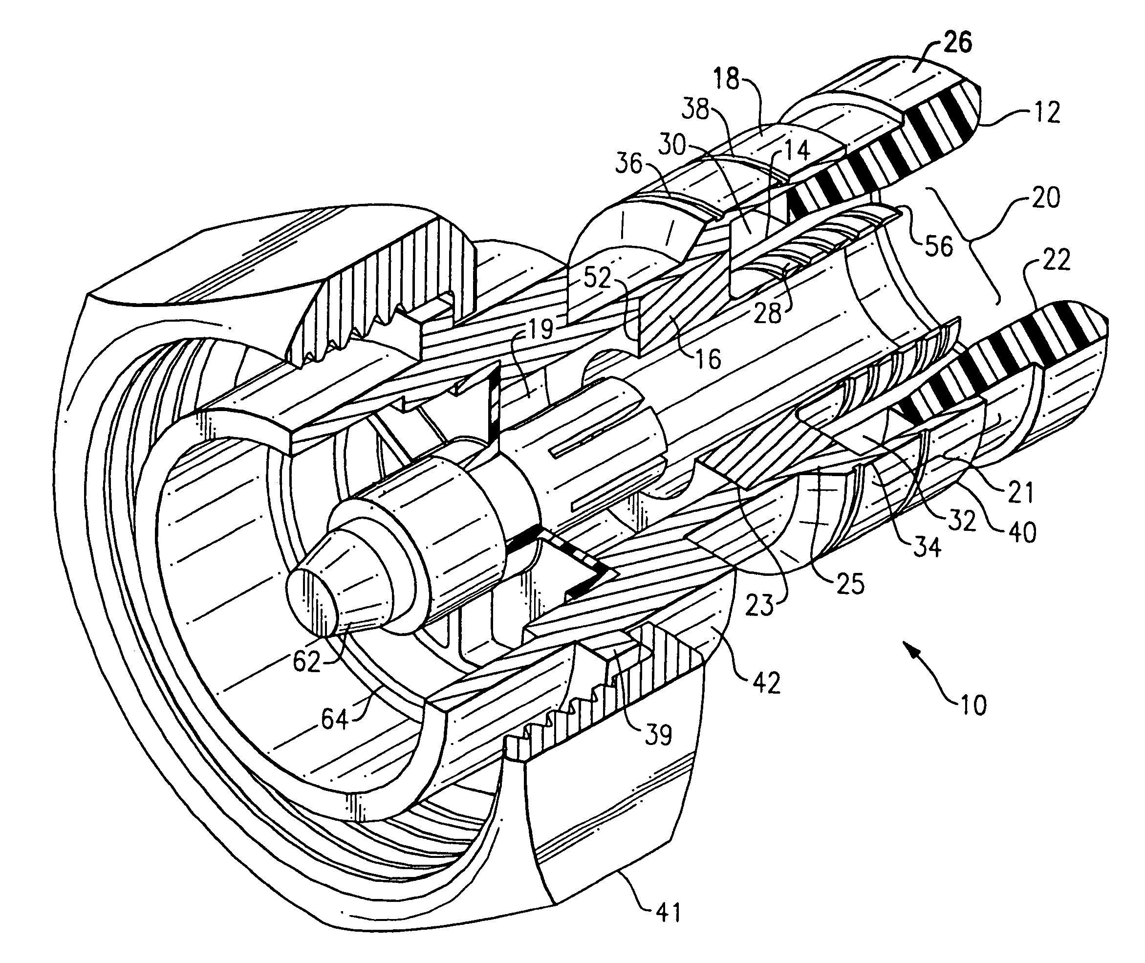
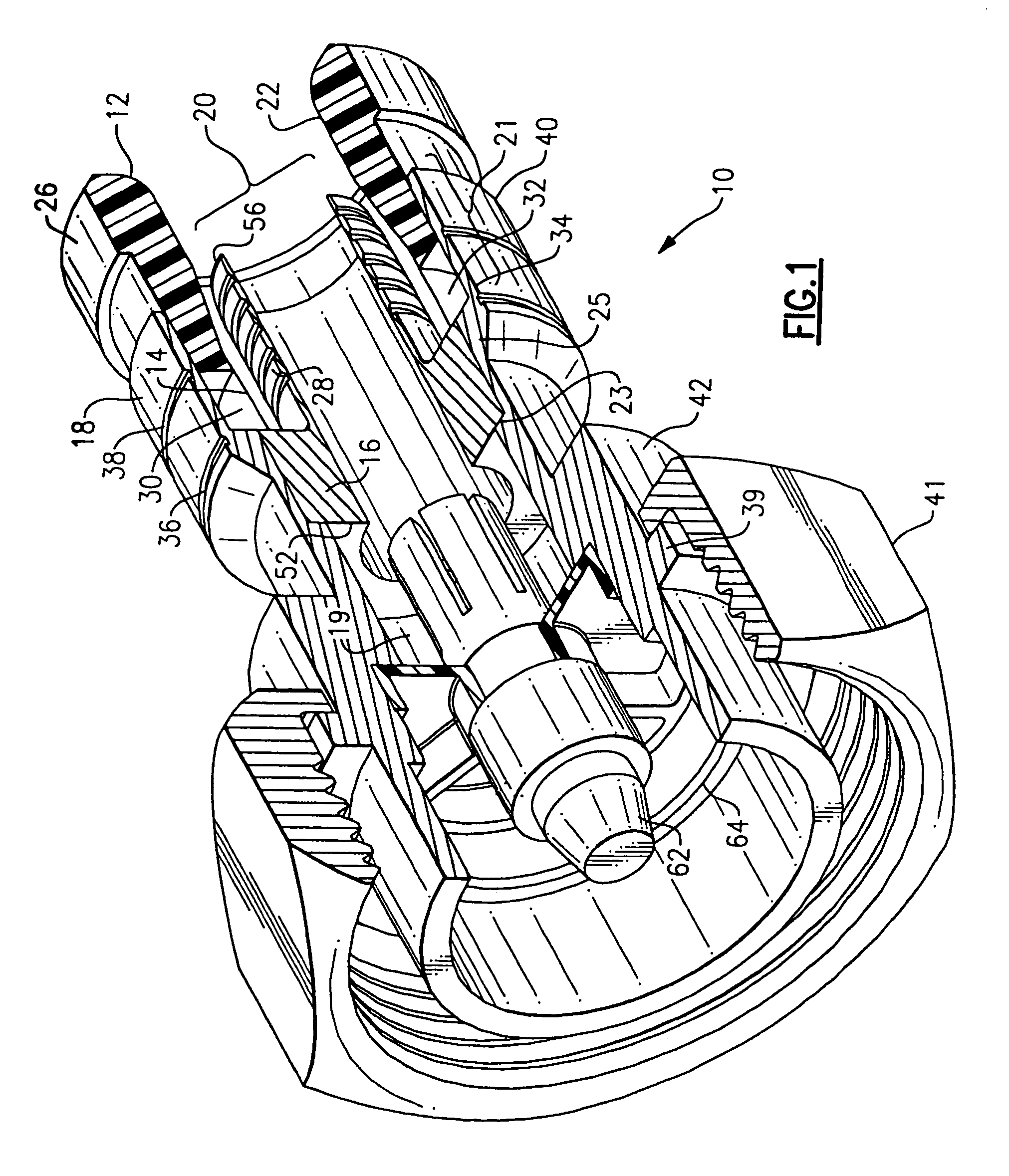
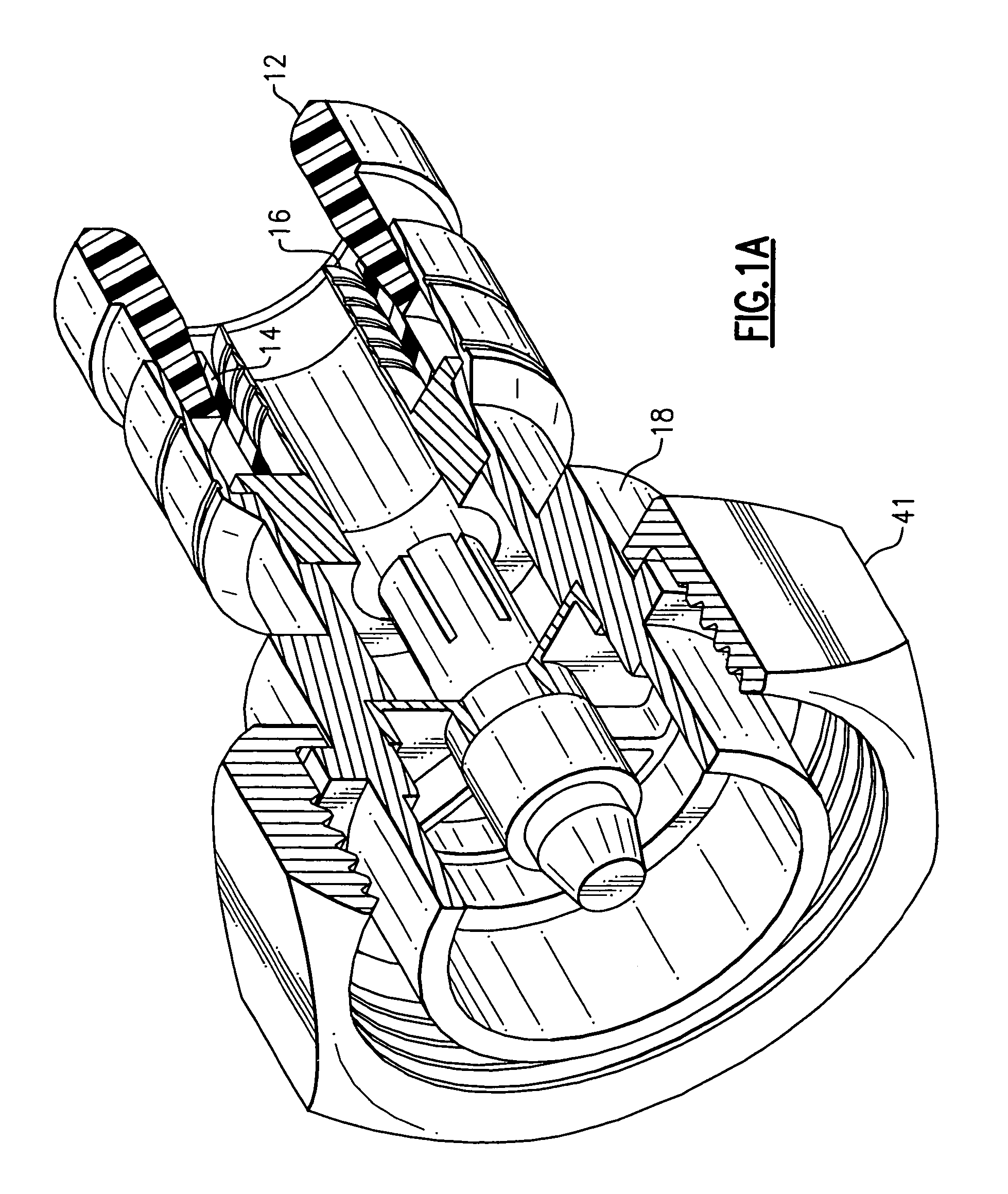
[0056]According to one embodiment, as shown in FIG. 1, the present invention for a compression connector 10 for a coaxial cable. The embodiment of the compression connector 10 shown in FIGS. 1 and 2 is configured as a DIN male connector interface; further embodiments of the present invention incorporating different connector interfaces are described below. Coaxial cable typically includes a center conductor surrounded by a dielectric layer, which is in turn surrounded by an outer conductor or grounding sheath. The outer conductor may include layers of conductive foils, a braided mesh of conductive wires or a combination of both. The outer conductor or grounding sheath is in turn surrounded by an...


PUM


Abstract

A compression connector for the end of a coaxial cable. The coaxial cable has a center conductor surrounded by a dielectric layer, the dielectric layer being surrounded by a conductive grounding sheath, and the conductive grounding sheath being surrounded by a protective outerjacket. The compression connector includes a body, a post and a compression member. The body and / or the compression member can have various shapes and orientations to enable the compression connector to readily accommodate coaxial cable having various thicknesses, due to, for example, being made by different manufacturers.

Description

CROSS-REFERENCE TO RELATED APPLICATIONS[0001]This application claims priority as a continuation in part application from and incorporates by reference the entirety of currently U.S. patent application Ser. No. 11 / 092,197, which was filed on Mar. 29, 2005, now U.S. Pat. No. 7,048,579, and which claimed priority as a continuation in part application from and incorporated by reference the entirety of currently U.S. patent application Ser. No. 10 / 892,645, which was filed on Jul. 16, 2004, now U.S. Pat. No. 7,029,326.FIELD OF THE INVENTION[0002]This invention relates to terminals for coaxial cables and more particularly to compression connectors for coaxial cables.BACKGROUND OF THE INVENTION[0003]The deployment of 50 ohm coaxial cable, such as, for example 200, 400 and 500 sizes of cable, for video and data transfer is increasing. Present 50 ohm connectors require labor intensive and craft sensitive installation. In one proposed approach, the 50 ohm connector is supplied as a kit and is ...

Claims


Application Information

Patent Timeline
Patent Type & Authority Patents(United States)
IPC IPC(8): H01R9/05
CPCH01R9/0518H01R9/0524H01R24/40H01R4/5016H01R13/622H01R13/623H01R24/562H01R2103/00H01R2107/00
Inventor MONTENA, NOAH
Owner RF IND
Learn More