
Main door lock housing for a vending machine

a technology for locking housing and vending machines, which is applied in the field of vending machines, can solve the problems of unauthorized access to the commodities stored within the vending machine, and create structural defects in the housing material, and achieve the effect of improving the structural stability of the second end, without sacrificing the structural integrity of the lock housing

Inactive Publication Date: 2006-11-07
CRANE MERCHANDISING SYSTEMS
View PDF6 Cites 0 Cited by
  • Summary
  • Abstract
  • Description
  • Claims
  • Application Information

AI Technical Summary

Benefits of technology

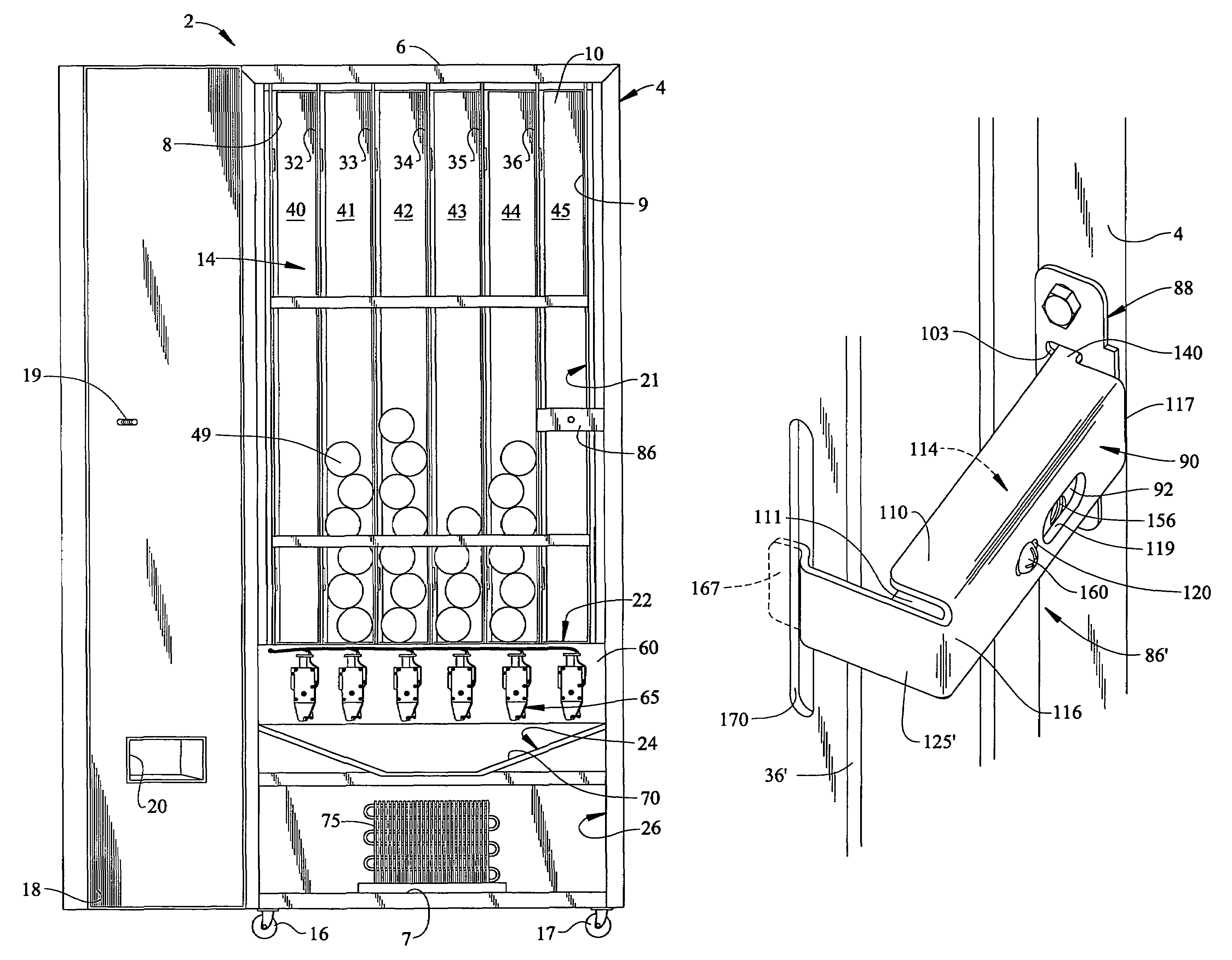
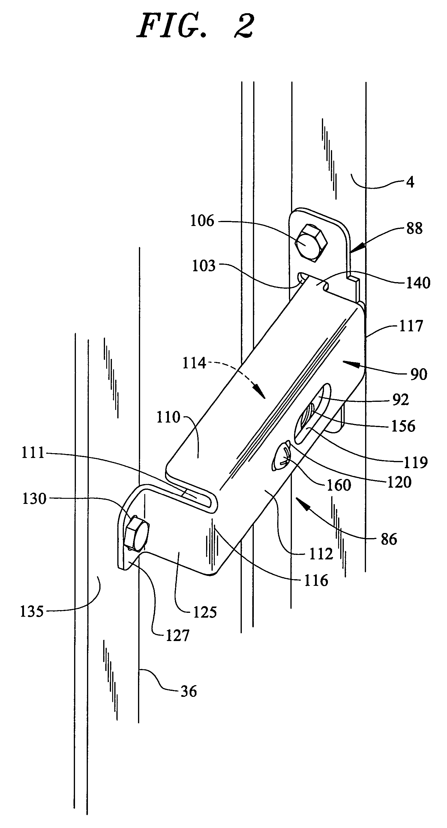
[0011]In accordance with one form of the invention, each of the first and second ends constitute axial bend sections which include out-turned elements that form attachment flanges. The first end of the lock housing includes an out-turned flange formed substantially parallel to the main body portion. The out-turned flange is provided with a bore through which a mechanical fastener can secure the first end of the lock housing to a structural member of the vending machine. The second end of the lock housing is defined by a bend section formed perpendicular to the main body portion and is provided with first and second mounting ears. Each of the first and second mounting ears include respective openings through which a mechanical fastener can secure the second end of the lock housing to a structural member of the vending machine. Preferably, the lock housing is secured between two respective column walls arranged opposite a hinge element. More preferably, the lock housing spans a stack area defined by the opposing column walls. In accordance with the invention the structural stability of the second end is improved though the incorporation of first and second slotted openings arranged on the bend second section. The slotted openings are adapted to engage respective tab portions formed on an end portion of the side wall adjacent to the second end. With this arrangement, force exerted on the second end is distributed more evenly over the entire lock housing.
[0012]In accordance with another form of the present invention, the first end extends to a first in-turned segment. Specifically, the first in-turned segment leads to an angled portion which terminates in a down-turned tab segment. With this arrangement the first end of the lock housing is secured to a side portion of a bottle retaining column located remote from a hinge element of the main door. More specifically, the side portion of the bottle retaining column includes a slot adapted to receive the down-turned tab segment of the first end. Therefore, in accordance with this embodiment, the need for additional mechanical fasteners is eliminated without sacrificing the structural integrity of the lock housing.

Problems solved by technology

Accordingly, extreme loading of the door may cause the lock housing to fail, and thus enable unauthorized access to the commodities stored within the machine.
In the event that the lock housing does not fail on a first attempt, high loads applied to the cantilevered housing will create structural defects in the housing material.

Method used


Image

  • Main door lock housing for a vending machine
  • Main door lock housing for a vending machine
  • Main door lock housing for a vending machine

Examples


first embodiment

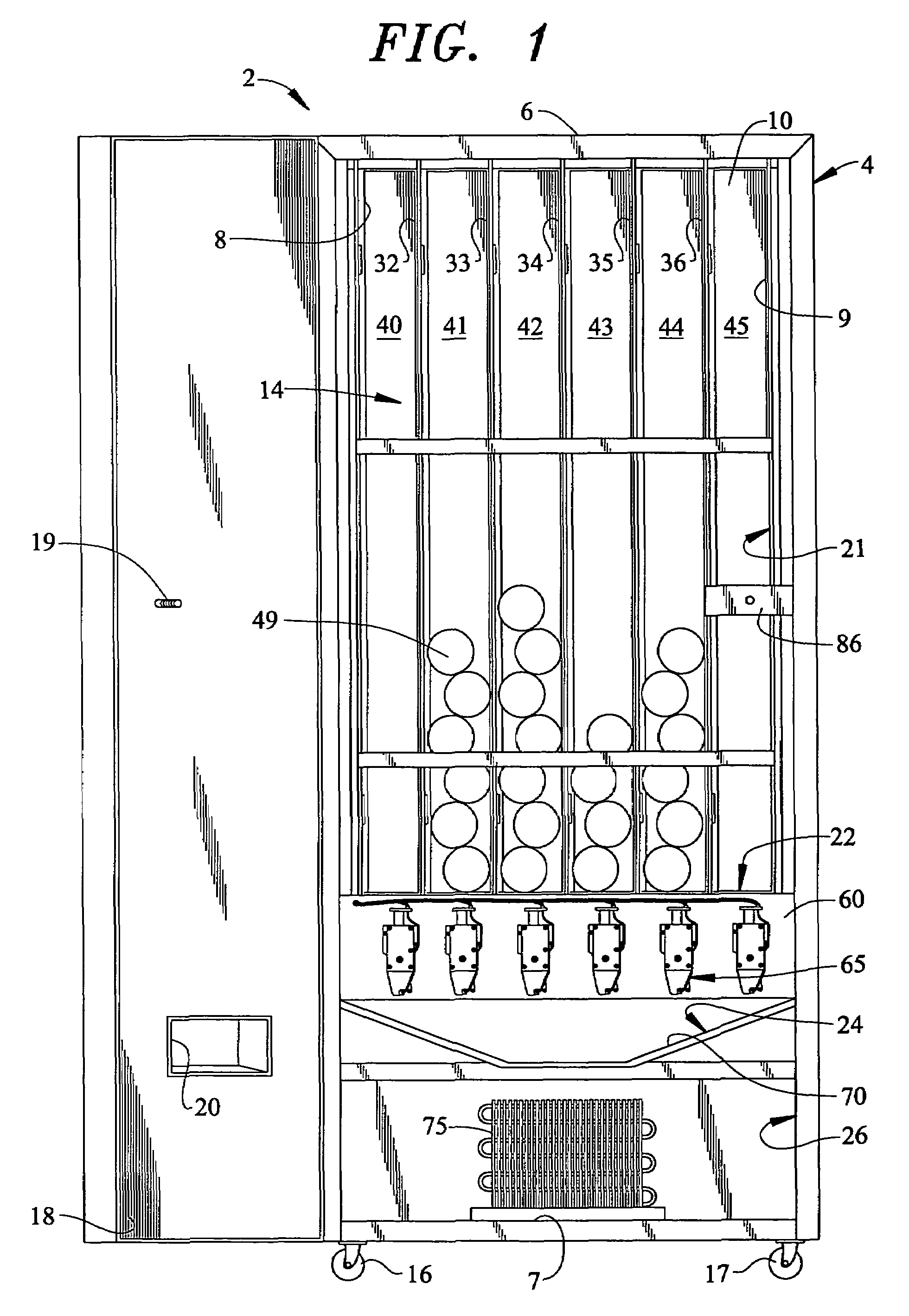
[0023]Referring to FIGS. 2–6, a lock housing assembly 86 constructed in accordance with the invention includes a support flange or bracket 88, a main body portion 90 and a lock member 92 which, in the most preferred form of the invention, is constituted by a floating lock element. As best shown in FIG. 6, support bracket 88 includes a planar surface 98 having arranged therein first and second mounting apertures 100 and 101, as well as a pair of slotted openings 103 and 104 positioned inwardly of mounting apertures 100 and 101. Mounting apertures 100 and 101 enable support bracket 88 to be secured to cabinet frame 4 through mechanical fasteners 106. With particular reference to FIGS. 2, 4 and 6, main body portion 90 has a generally U-shaped cross section including first and second side walls 110 and 111 that are interconnected through an intermediate wall 112. More specifically, first and second side walls 110 and 111 and intermediate wall 112 collectively define a rear channel or ca...

second embodiment

[0026]Reference will now be made to FIGS. 3 and 5 in describing the present invention. In some vending machine arrangements, the column walls have a thin profile and are typically not provided with a front face portion that corresponds to face portion 135. To address this fact, a lock housing assembly 86′ constructed in accordance with this embodiment of the invention includes a modified attachment flange 125′. More specifically, attachment flange 125′ is provided with an in-turned tab member 167 adapted to engage or hook into a slotted opening 170 provided on a side surface (not labeled) of column wall 36′. In this manner, main housing 90 can be fully supported at both first and second end portions 116 and 117 across stack area 45 despite the lack of a front face portion on column wall 36′.

[0027]Regardless of the particular arrangement, each of lock housing assemblies 86 and 86′ provides a uniquely strong base to which door 18 can be secured. For instance, as main body portion 90 s...


PUM


Abstract

A vending machine includes a cabinet frame having top, bottom, side and rear walls that collectively define a central cavity. A plurality of column walls are arranged within the central cavity that, together with the side walls, form an associated plurality of stack or column areas for receiving product containers to be vended. The vending machine includes a door that is pivotally mounted to the cabinet frame for selectively closing off the central cavity. In order to prevent unauthorized access to the product stored in the central cavity, the vending machine is provided with a lock assembly including a main body and a lock member. The main body includes first and second fixed end portions and an intermediate portion that spans one of the plurality of stack areas. The lock member is attached to the main body and receives a locking element of the door.

Description

CROSS-REFERENCE TO RELATED APPLICATION[0001]The present application claims benefit to U.S. Provisional Patent Application Ser. No. 60 / 415,770 entitled “MAIN DOOR LOCK HOUSING FOR A VENDING MACHINE” filed on Oct. 4, 2002.BACKGROUND OF THE INVENTION[0002]1. Field of the Invention[0003]The present invention pertains to the art of vending machines and, more particularly, to a lock housing for a vending machine having first and second ends, each of which is secured to an internal structural member of the vending machine.[0004]2. Discussion of the Prior Art[0005]In general, it is known to secure a main door of a vending machine with a lock having a fixed lock housing. Typically, the lock housing is secured to a structural member of the vending machine. With this arrangement, unauthorized access to commodities stored within the machine is prevented, thus reducing the occurrence of pilfering and the like.[0006]There are a wide variety of lock arrangements currently in use. Manufactures empl...

Claims


Application Information

Patent Timeline
Patent Type & Authority Patents(United States)
IPC IPC(8): E05B65/06G07F9/10
CPCG07F9/10
Inventor RICHARDSON, EDMUND SCOTT
Owner CRANE MERCHANDISING SYSTEMS
Learn More