
Throttle system abnormality determination apparatus

a technology of abnormality determination and throttle system, which is applied in the direction of machines/engines, electric control, instruments, etc., can solve the problems of deterioration of drivability of the vehicle driver, and achieve the effect of improving drivability at the time of abnormality in the throttle system, improving abnormality determination accuracy, and deteriorating drivability

Inactive Publication Date: 2006-11-07
DENSO CORP
View PDF5 Cites 4 Cited by
  • Summary
  • Abstract
  • Description
  • Claims
  • Application Information

AI Technical Summary

Benefits of technology

The present invention provides an abnormality determination apparatus for a throttle system that can detect abnormalities in the system in an early manner, before they significantly impact the operating state of an internal combustion engine. The apparatus uses determining means to determine if there is an abnormality in the throttle system based on an abnormality determination condition. The condition is changed based on the operating states of the vehicle and / or engine to improve the accuracy of detecting abnormalities and to improve the likelihood of starting suitable failsafe processing before the drivability is deteriorated. This results in improved drivability at the time of the abnormality in the throttle system.

Problems solved by technology

However, as explained above, the abnormality in the throttle control system occurring in the low-speed period has a significant influence on the operating state of the engine.
As a result, there is a possibility that a vehicle driver feels deterioration of drivability such as acceleration shock.

Method used


Image

  • Throttle system abnormality determination apparatus
  • Throttle system abnormality determination apparatus
  • Throttle system abnormality determination apparatus

Examples


first embodiment

[0021](First Embodiment)

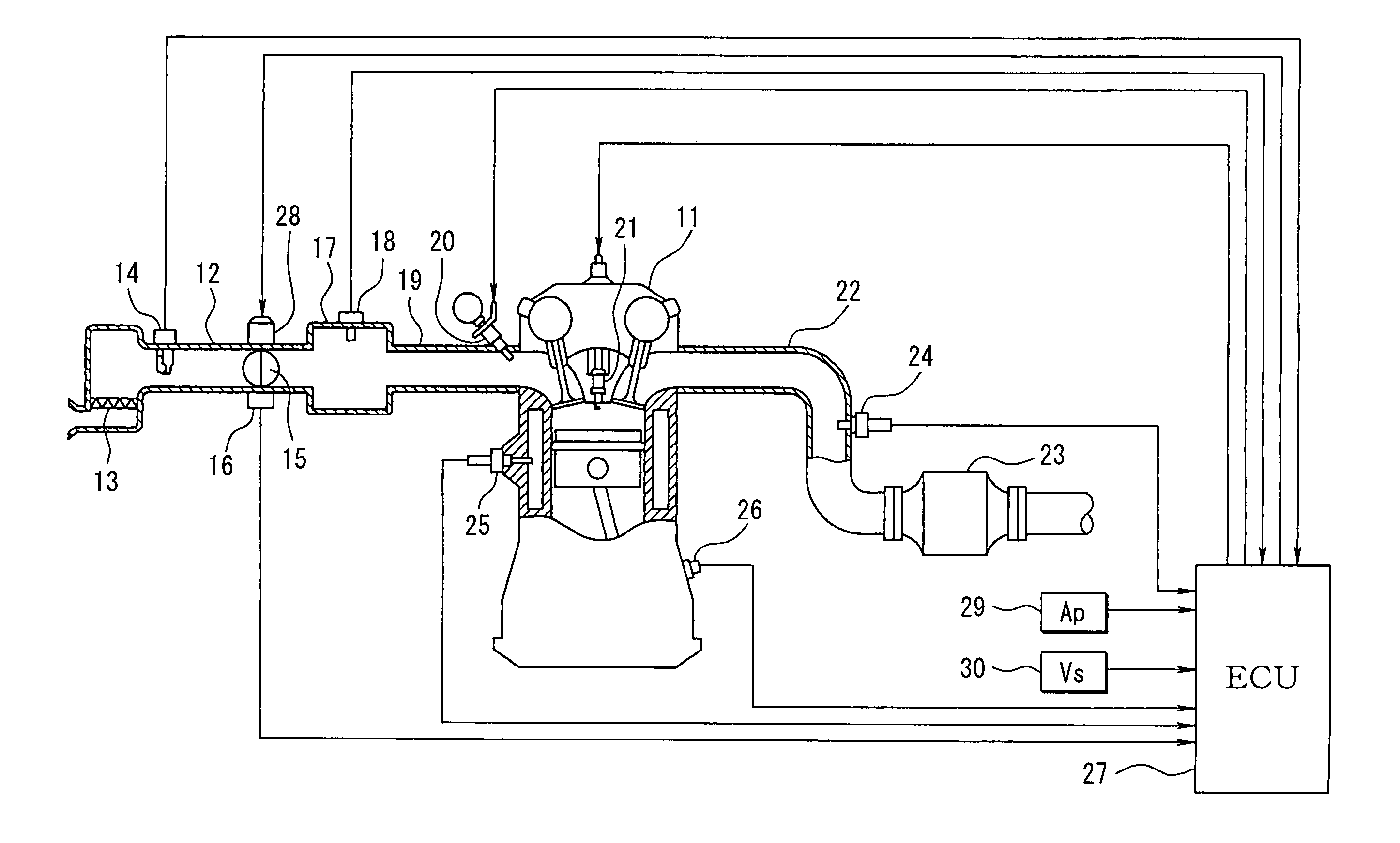
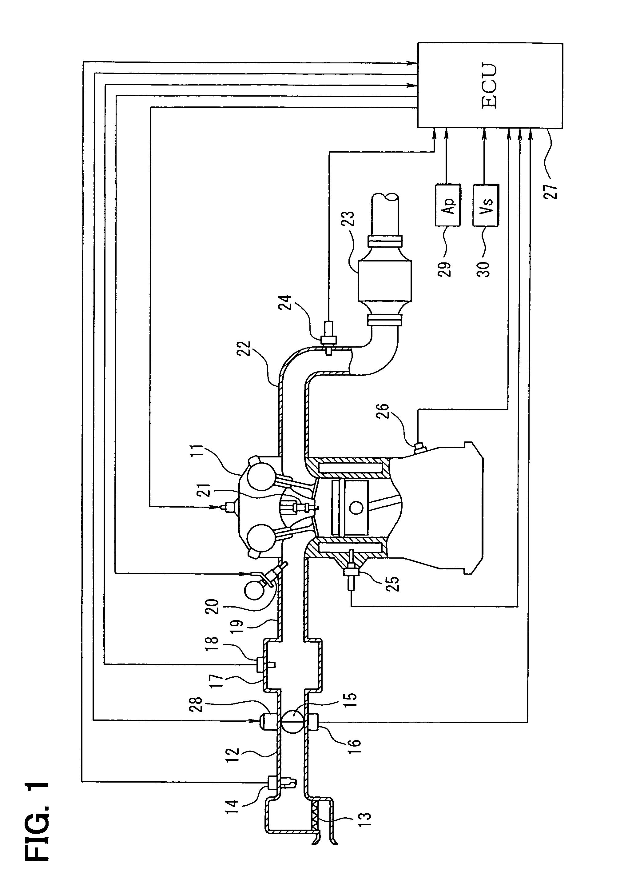
[0022]Referring to FIG. 1, an engine control system according to a first embodiment of the present invention is illustrated. As shown in FIG. 1, an air cleaner 13 is disposed in the most upstream portion of an intake pipe 12 of an internal combustion engine 11. An air flow meter 14 for sensing an air intake quantity is disposed downstream of the air cleaner 13. A throttle valve 15 and a throttle position sensor 16 are disposed downstream of the air flow meter 14. A throttle motor (a throttle actuator) 28 such as a DC motor regulates an angle of the throttle valve 15. The throttle position sensor 16 senses the angle of the throttle valve 15 (a throttle opening degree).

[0023]A surge tank 17 is disposed downstream of the throttle valve 15. An intake pipe pressure sensor 18 for sensing an intake pipe pressure (a pressure in the intake pipe 12) is mounted to the surge tank 17. An intake manifold 19 for leading the air into respective cylinders of the engine 11 is ...

second embodiment

[0045](Second Embodiment)

[0046]Next, processing based on a throttle motor overcurrent abnormality determination program, which is executed by the ECU 27, according to a second embodiment of the present invention will be explained based on FIGS. 5 to 7.

[0047]In the second embodiment, the ECU 27 executes the program shown in FIG. 5 to calculate duration of a state in which an overcurrent flows through the throttle motor 28. Then, the ECU 27 determines existence or nonexistence of an abnormality in the throttle control system (an overcurrent abnormality of the throttle motor 28) by comparing the duration with an abnormality determination period FLT. The ECU 27 changes the abnormality determination period FLT in accordance with the vehicle speed Vs sensed by the vehicle speed sensor 30. Thus, if the vehicle speed Vs decreases (if the throttle opening degree decreases) and the influence of the abnormality in the throttle control system on the operating state of the engine 11 increases, t...


PUM


Abstract

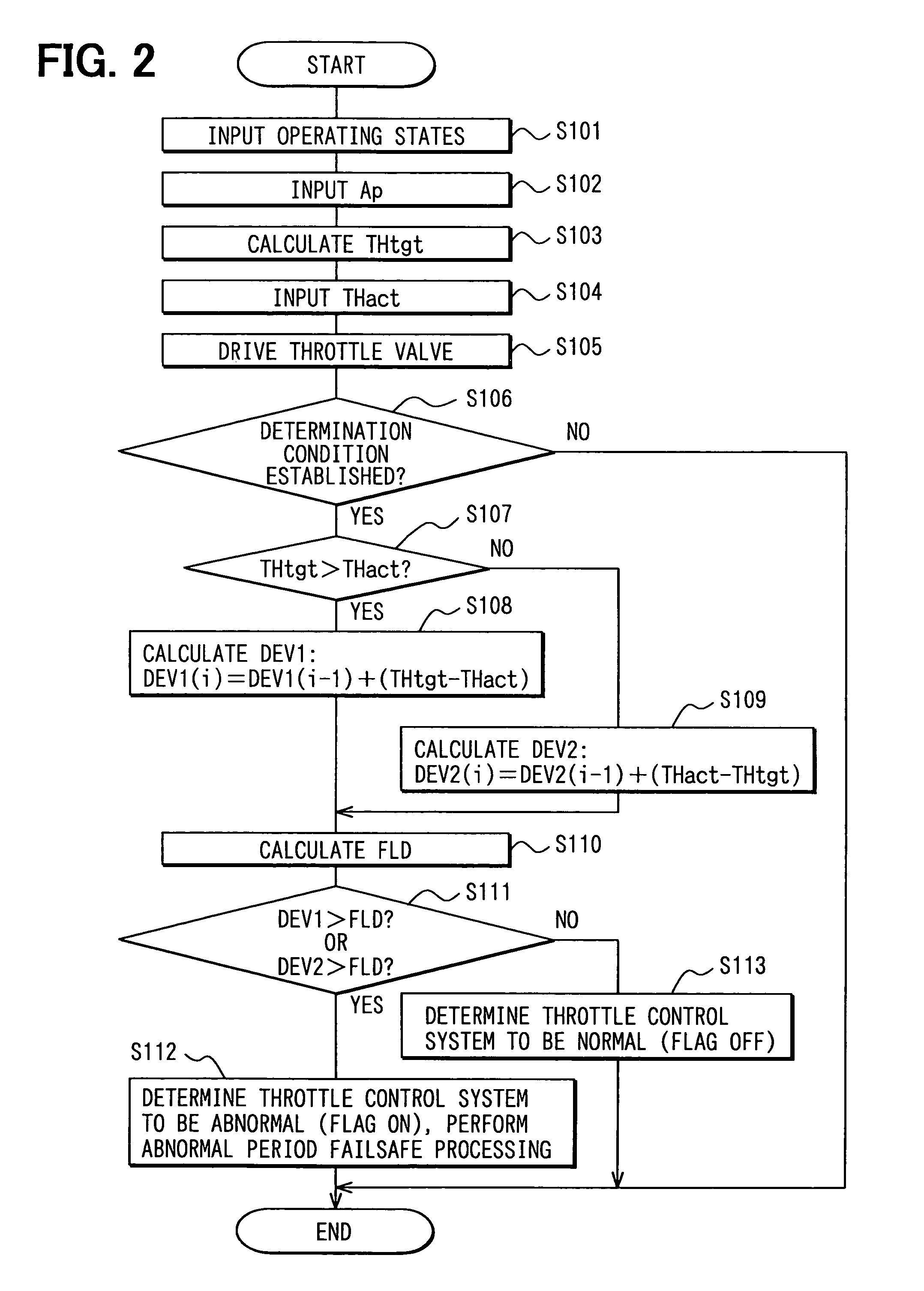
An abnormality determination apparatus of a throttle control system calculates an integrated value of a deviation between an actual throttle angle and a target throttle angle. The abnormality determination apparatus determines existence or nonexistence of an abnormality in the throttle control system by comparing the integrated value with an abnormality determination value. The abnormality determination value is changed so that the abnormality determination value becomes smaller in a low-speed traveling period than in a high-speed traveling period. Thus, in the low-speed traveling period, in which an influence of the abnormality in the throttle control system on an operating state of an engine becomes larger than in the high-speed traveling period, the abnormality in the throttle control system can be detected and failsafe processing can be started in an early stage of the abnormality.

Description

CROSS REFERENCE TO RELATED APPLICATION[0001]This application is based on and incorporates herein by reference Japanese Patent Application No. 2003-427549 filed on Dec. 24, 2003.BACKGROUND OF THE INVENTION[0002]1. Field of the Invention[0003]The present invention relates a throttle system abnormality determination apparatus for determining existence or nonexistence of an abnormality in a throttle control system, which controls a throttle valve of an internal combustion engine, or in parts related to the throttle control system.[0004]2. Description of Related Art[0005]A certain internal combustion engine mounted to a vehicle has an electronic throttle control system for electronically controlling a throttle angle (an opening degree of a throttle valve) TH. The system includes a throttle motor for driving the throttle valve. The system calculates a target throttle angle based on an amount of manipulation of an accelerator and others, and senses an actual throttle angle by a throttle po...

Claims


Application Information

Patent Timeline
Patent Type & Authority Patents(United States)
IPC IPC(8): G01M15/00F02D9/02F02D11/10F02D41/22F02D45/00G01M99/00
CPCF02D11/107F02D41/221Y02T10/40
Inventor OKUMURA, HIROSHI
Owner DENSO CORP
Learn More