
Method of dynamically controlling cache size

a dynamic control and cache technology, applied in memory adressing/allocation/relocation, high-level techniques, instruments, etc., can solve the problems of static power dissipation, high-performance processors are increasing in complexity, and the leakage current is increasing, so as to reduce power consumption, not impact performance, and high performance.

Active Publication Date: 2006-10-24
GLOBALFOUNDRIES US INC
View PDF6 Cites 80 Cited by
  • Summary
  • Abstract
  • Description
  • Claims
  • Application Information

AI Technical Summary

Benefits of technology

The invention provides a method and apparatus for powering down sections of a microprocessor cache to minimize power consumption, while not impacting performance when high performance is required. This is achieved by using a power saving cache that dynamically reduces the logical size of the cache in order to save power. The invention also includes steps for maintaining coherency during cache resizing and provides options for partitioning the cache for optimal performance. The technical effects of the invention include reducing power consumption and improving performance efficiency of microprocessors.

Problems solved by technology

Due to the shrinking geometry, advanced CMOS processors have increasingly higher leakage currents and thus static power dissipation.
High performance processors are increasing in complexity according to “Moore's Law” (complexity doubles every eighteen months) increasing the number of transistors and thus power consumption.
The net result is that the caches are consuming a larger portion of the processor's power.
Currently, the cache size and cache power consumption remain constant during microprocessor usage.
Furthermore, during low power operation, the full DC portion of the power consumption is still dissipated, serving no purpose.

Method used


Image

  • Method of dynamically controlling cache size
  • Method of dynamically controlling cache size
  • Method of dynamically controlling cache size

Examples


Embodiment Construction

[0019]Partitioning Caches for Power Savings

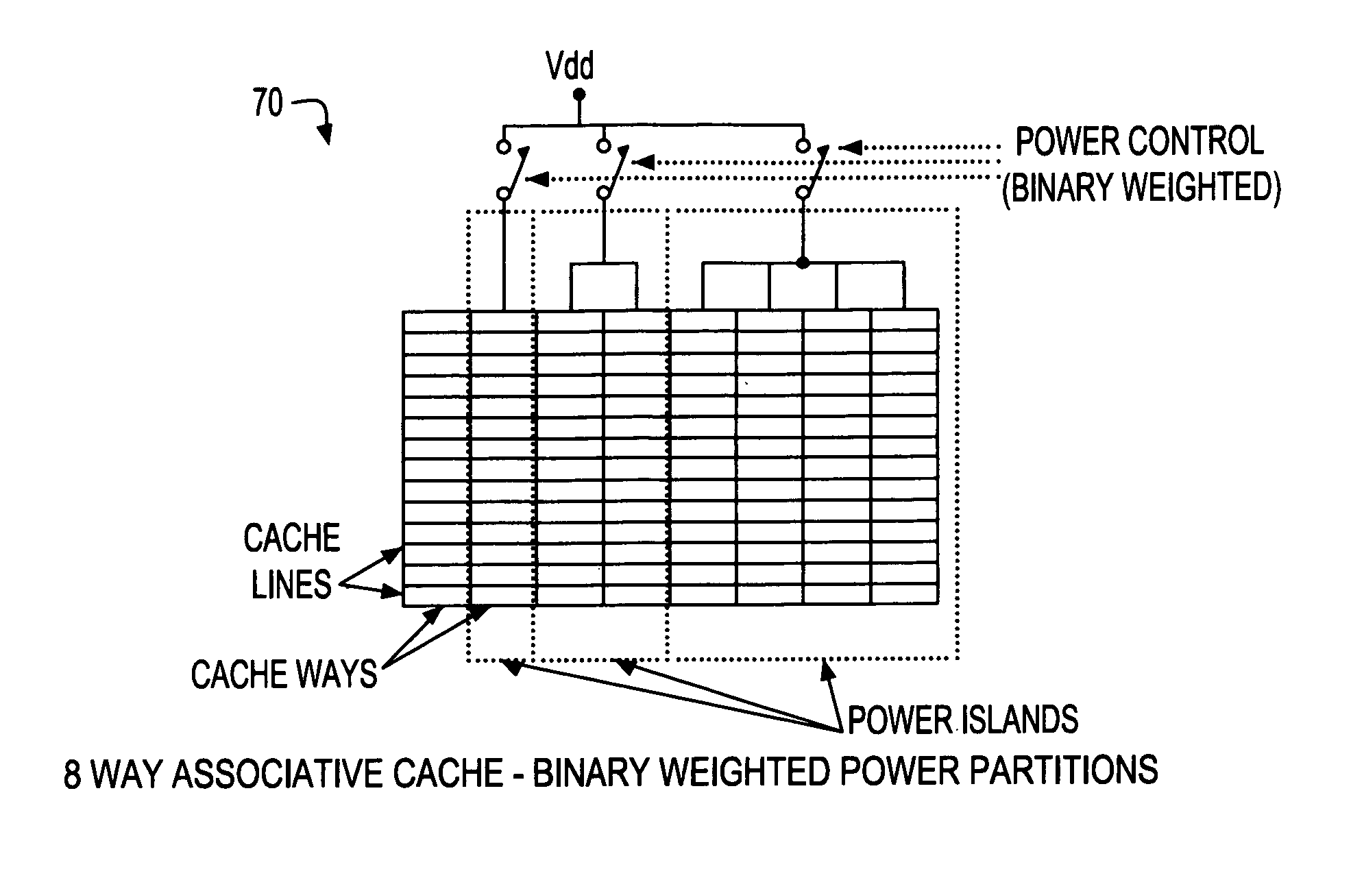
[0020]In accordance with the present invention, to realize the power savings, the cache arrays of a processor are designed such that they can be partially powered off without compromising data integrity or system operation. Two specific methods, referred to as “horizontal” and “vertical” partitioning, are described below in detail.

[0021]Horizontal Partition

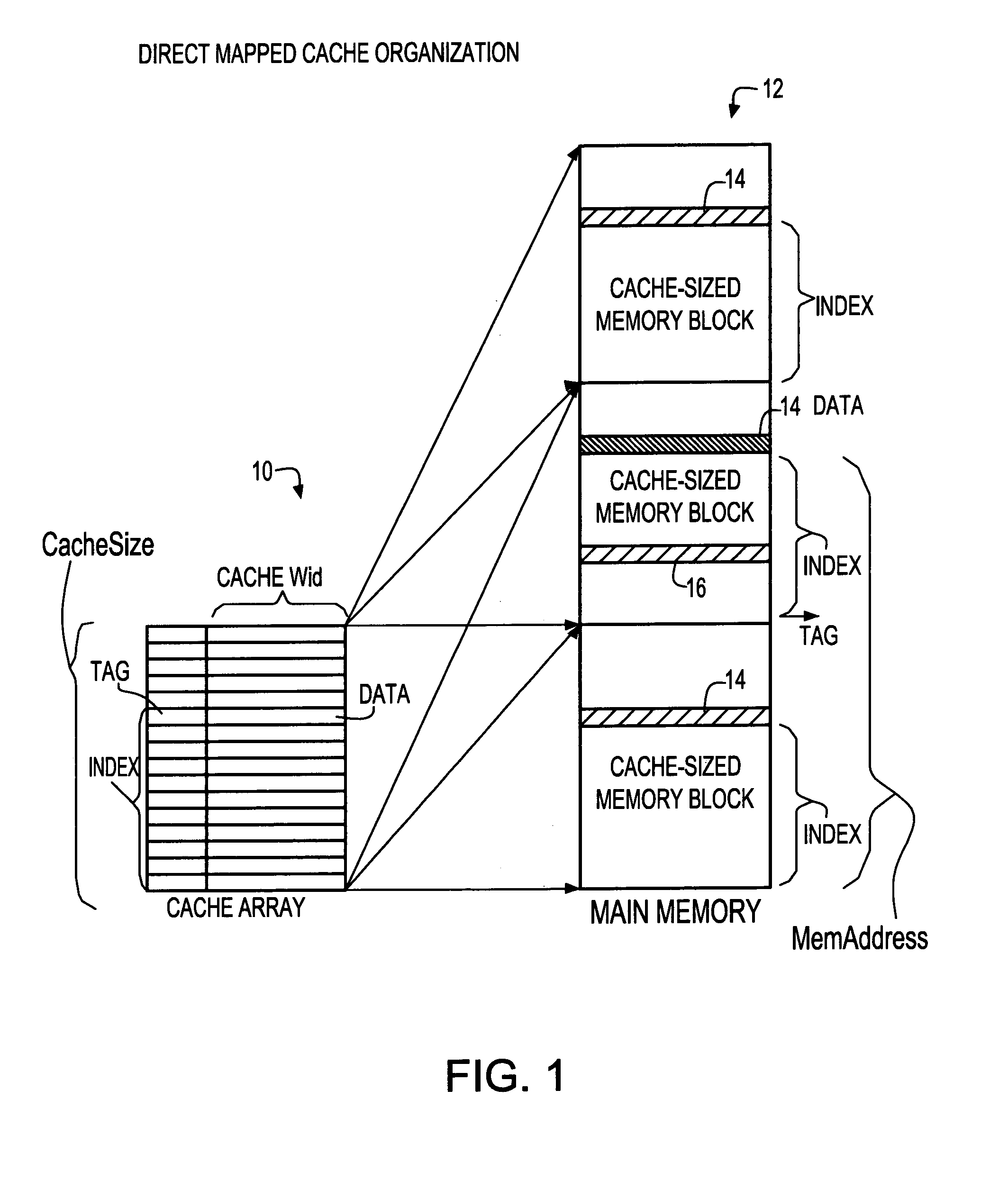
[0022]A direct mapped cache implies that each memory location can be cached in exactly one cache location. However, each cache line may be mapped into a number of memory locations.

[0023]FIG. 1 shows a representation 10 of a simplified direct mapped cache array of size “CacheSize” and a map of a processor's memory 12. The memory array 12 is broken down into CacheSize blocks. Data in the memory array can be stored in the cache at the same index as it is in memory (offset from the beginning of the CacheSize block of memory). The “Tag” value of that cache location then stores the number of th...


PUM


Abstract

A power saving cache and a method of operating a power saving cache. The power saving cache includes circuitry to dynamically reduce the logical size of the cache in order to save power. Preferably, a method is used to determine optimal cache size for balancing power and performance, using a variety of combinable hardware and software techniques. Also, in a preferred embodiment, steps are used for maintaining coherency during cache resizing, including the handling of modified (“dirty”) data in the cache, and steps are provided for partitioning a cache in one of several way to provide an appropriate configuration and granularity when resizing.

Description

BACKGROUND OF INVENTION[0001]1. Field of the Invention[0002]This invention generally relates to microprocessor caches, and more specifically, to dynamically controlling cache size.[0003]2. Background Art[0004]There is an industry wide drive to lower power consumption in microprocessors for improved performance, speeds, battery life, environmental needs, power supply limitations, etc. Due to the shrinking geometry, advanced CMOS processors have increasingly higher leakage currents and thus static power dissipation. High performance processors are increasing in complexity according to “Moore's Law” (complexity doubles every eighteen months) increasing the number of transistors and thus power consumption. Additionally, processor caches are growing at a rate faster than that of the processor logic. The net result is that the caches are consuming a larger portion of the processor's power.[0005]Currently, the cache size and cache power consumption remain constant during microprocessor usa...

Claims


Application Information

Patent Timeline
Patent Type & Authority Patents(United States)
IPC IPC(8): G06F12/00G06F1/32G06F12/08
CPCG06F1/3225G06F1/3275G06F12/0864G06F12/0804G06F2212/1028Y02B60/1228Y10S707/99952Y02B60/32Y02B60/1225Y02D10/00Y02D30/50
Inventor COHEN, ERWIN B.COOK, THOMAS E.GOVETT, IAN R.KARTSCHOKE, PAUL D.KOSONOCKY, STEPHEN V.SANDON, PETER A.WILLIAMS, KEITH R.
Owner GLOBALFOUNDRIES US INC
Learn More