Batch target and method for producing radionuclide

Inactive Publication Date: 2006-10-24
DUKE UNIV
View PDF14 Cites 28 Cited by
  • Summary
  • Abstract
  • Description
  • Claims
  • Application Information

AI Technical Summary

Problems solved by technology

Thus, according to this estimate, the cyclotron operation represents about 20% of the cost of the PET scan.
The full production potential of these accelerators is not realized, at least in part because current target system technology cannot dissipate the heat that would be produced were the full available beam current to be used.
It is this heat that limits the amount of radioactive product that can be produced in a given amount of time.
If beam power were applied to a completely filled conventional target, boiling in the target volume would cause a very rapid rise in pressure due to the sudden appearance of vapor bubbles.
As a result, target pressure will dramatically increase, thereby causing the window to plastically deform until it ruptures or otherwise fails.
Thus, the conventional target is typically incompletely filled and sealed such that the mass of water therein is fixed.
As a result, the conventional target is limited to a single optimum beam power level that prevents destruction, and this optimum power level does not correspond to the most efficient production of radionuclides for the given target system and beam source and for all beam power levels.
In addition, because the bottom of the conventional target is sealed, the target water expands upwardly when heated into a reflux chamber, thereby reducing the vapor space available for heat transfer.
Moreover, such conventional targets have the disadvantage of introducing pressurizing gas molecules other than water vapor into the target volume, which can be potentially contaminating and which impedes heat transfer efficiency.
Such target systems as disclosed in U.S. Pat. No. 5,917,874, deliberately designed for use in conjunction with a low-power beam source, cannot take advantage of the full power available from commercially available high-power beam sources.

Method used


Image

  • Batch target and method for producing radionuclide
  • Batch target and method for producing radionuclide
  • Batch target and method for producing radionuclide

Examples


Embodiment Construction

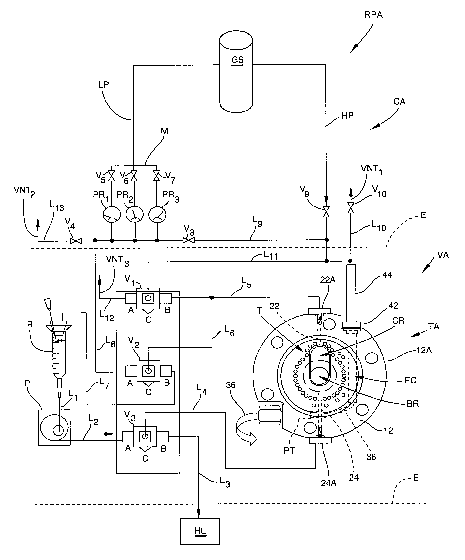
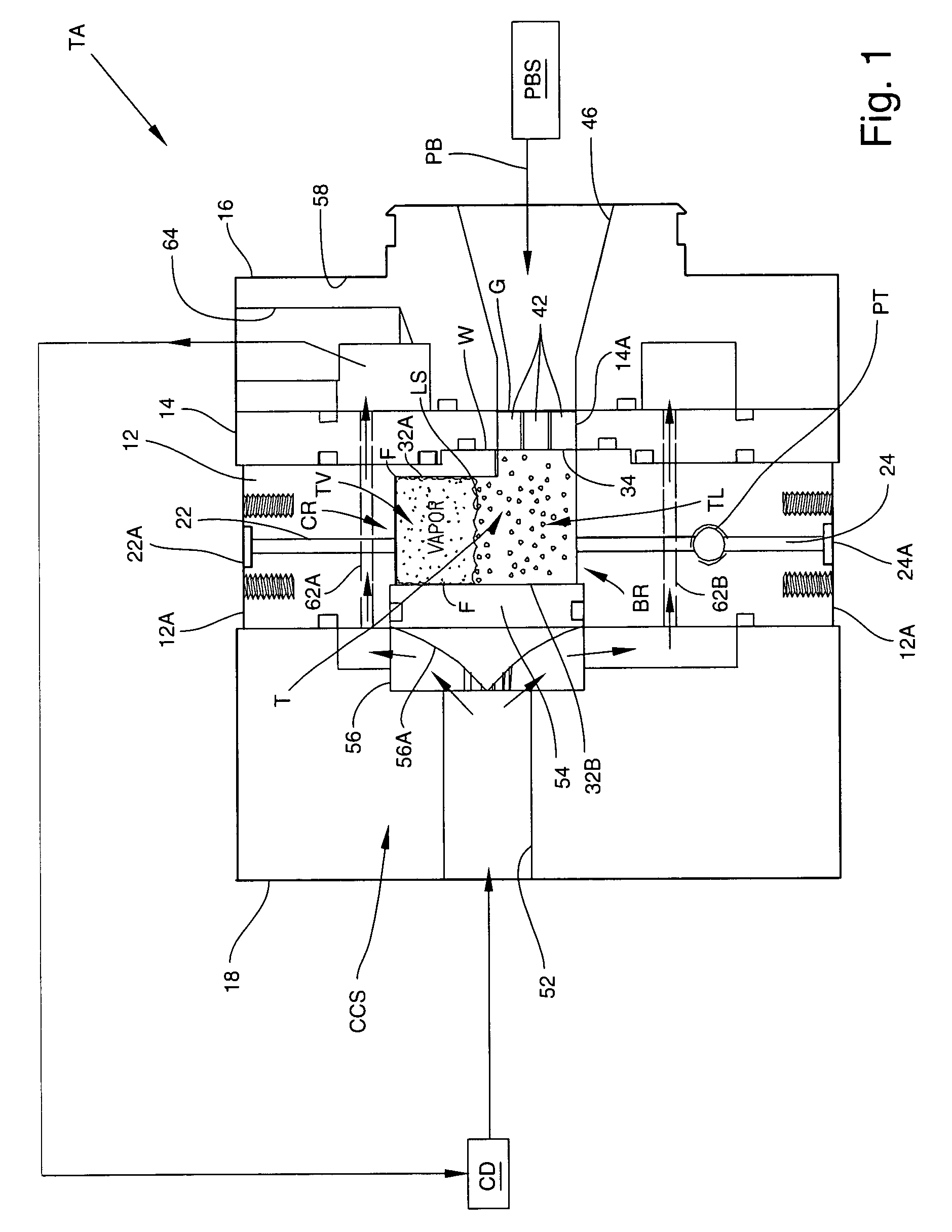
[0017]As used herein, the term “target material” means any suitable material with which a target fluid can be enriched to enable transport of the target material, and which, when irritated by a particle beam, reacts to produce a desired radionuclide. One non-limiting example of a target material is 18O (oxygen-18 or O-18), which can be carried in a target fluid such as water (H2 18O). When O-18 is irradiated by a suitable particle beam such as proton beam, O-18 reacts to produce the radionuclide 18F (fluorine-18 or F-18) according to the nuclear reaction O-18(P,N)F-18 or, in equivalent notation, 18O(p,n)18F.

[0018]As used herein, the term “target fluid” generally means any suitable flowable medium that can be enriched by, or otherwise be capable of transporting, a target material or a radionuclide. One non-limiting example of a target fluid is water.

[0019]As used herein, the term “fluid” generally means any flowable medium such as liquid, gas, vapor, supercritical fluid, or combinati...


PUM


Abstract

An apparatus for producing a radionuclide includes a target chamber including a beam strike region for containing a liquid and a condenser region for containing a vapor. A particle beam source is operatively aligned with the beam strike region, and a lower liquid conduit communicates with the beam strike region. The condenser region is disposed above the beam strike region in fluid communication therewith for receiving heat energy from the beam strike region and transferring condensate to the beam strike region. The lower liquid conduit transfers liquid to and from the beam strike region. In operation, the target chamber acts as a thermosyphon that is self-regulating in response to heat energy deposited by the particle beam source. A portion of the liquid expands into the lower liquid conduit prior to boiling. After boiling begins, a vapor void is created above the liquid and an evaporation / condensation cycle is established, with additional liquid being displaced into the lower liquid conduit.

Description

RELATED APPLICATIONS[0001]This application claims the benefit of U.S. Provisional Patent Application Ser. Nos. 60 / 382,224 and 60 / 382,226, both filed May 21, 2002; the disclosures of which are incorporated herein by reference in their entireties.TECHNICAL FIELD[0002]The present invention relates generally to radionuclide production. More specifically, the invention relates to apparatus and methods for producing a radionuclide such as F-18 using a thermosyphonic beam strike target.BACKGROUND ART[0003]Radionuclides such as F-18, N-13, O-15, and C-11 can be produced by a variety of techniques and for a variety of purposes. An increasingly important radionuclide is the F-18 (18F−) ion, which has a half-life of 109.8 minutes. F-18 is typically produced by operating a cyclotron to proton-bombard stable O-18 enriched water (H218O), according to the nuclear reaction 18O(p,n)18F. After bombardment, the F-18 can be recovered from the water. For at least the past two decades, F-18 has been prod...

Claims


Application Information

Patent Timeline
IPC IPC(8): G21G1/10A61M36/00H05H6/00
CPCG21G1/10H05H6/00
Inventor WIELAND, BRUCE W.
Owner DUKE UNIV
Why Eureka
Try Eureka