
Hydraulic energy intensifier

a technology of hydraulic energy intensifier and energy recovery circuit, which is applied in the direction of fluid couplings, couplings, mechanical equipment, etc., to achieve the effect of increasing the amount of hydraulic energy stored, lowering the energy load, and increasing the energy of the hydraulic pump

Inactive Publication Date: 2006-10-24
DEERE & CO
View PDF7 Cites 65 Cited by
  • Summary
  • Abstract
  • Description
  • Claims
  • Application Information

AI Technical Summary

Benefits of technology

[0005]Provided herein is a hydraulic circuit that uses the stored energy from the low energy phase to lower the energy load on the hydraulic pump during the high energy phase. Energy from the hydraulic pump is increased during the low energy phase to increase the amount of stored hydraulic energy. The increased amount of stored energy is then used to intensify the energy generated, by the hydraulic pump, for the high energy phase. The use of the stored energy in this manner tends to narrow the difference between the energy loads on the hydraulic pump during the low and high energy phases. This makes it possible to reduce the hydraulic pump size and benefit from increased fuel efficiency without a consequential reduction in performance for the hydraulic circuit. It also makes it possible to increase the performance of the hydraulic circuit, or reduce the size of an engine driving the hydraulic circuit, without a consequential reduction in fuel efficiency.

Problems solved by technology

However, in conventional work vehicles, the stored hydraulic energy is not used to lower the energy load on the hydraulic pump supplying hydraulic energy to the cylinder.

Method used


Image

  • Hydraulic energy intensifier
  • Hydraulic energy intensifier
  • Hydraulic energy intensifier

Examples


Embodiment Construction

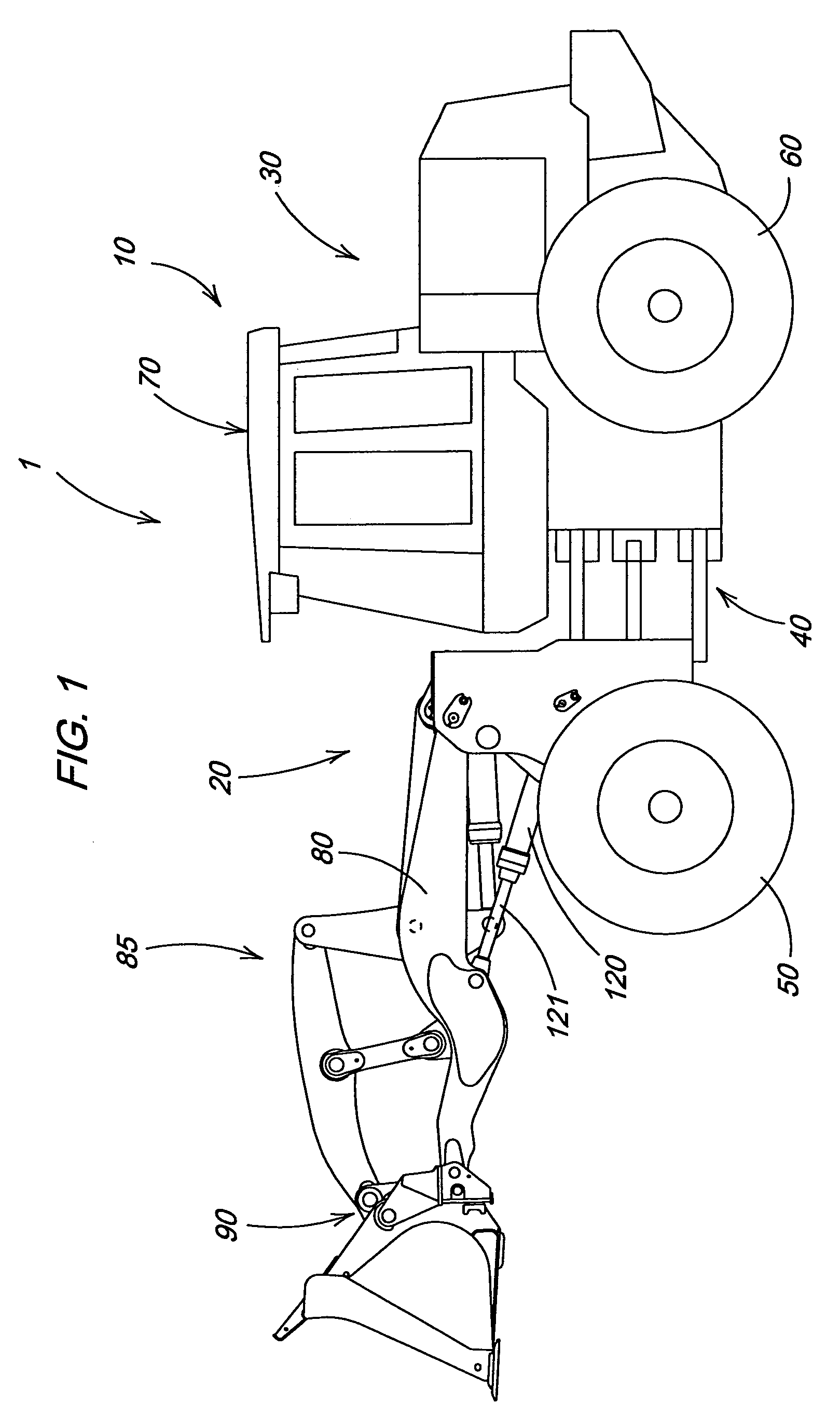
[0010]FIG. 1 illustrates a work vehicle in which the invention may be used. The particular work vehicle illustrated in FIG. 1 is an articulated four wheel drive loader 1 having a main vehicle body 10 that includes a front vehicle portion 20 pivotally connected to a rear vehicle portion 30 by vertical pivots 40, the loader being steered by pivoting of the front vehicle portion 20 relative to the rear vehicle portion 30 in a manner well known in the art. The front and rear vehicle portions 20 and 30 are respectively supported on front drive wheels 50 and rear drive wheels 60. An operator's station 70 is provided on the rear vehicle portion 30 and is generally located above the vertical pivots 40. The front vehicle portion 20 includes a boom 80, a linkage assembly 85, a work tool 90 and a hydraulic cylinder 120. The front and rear drive wheels 50 and 60 propel the vehicle along the ground and are powered in a manner well known in the art.

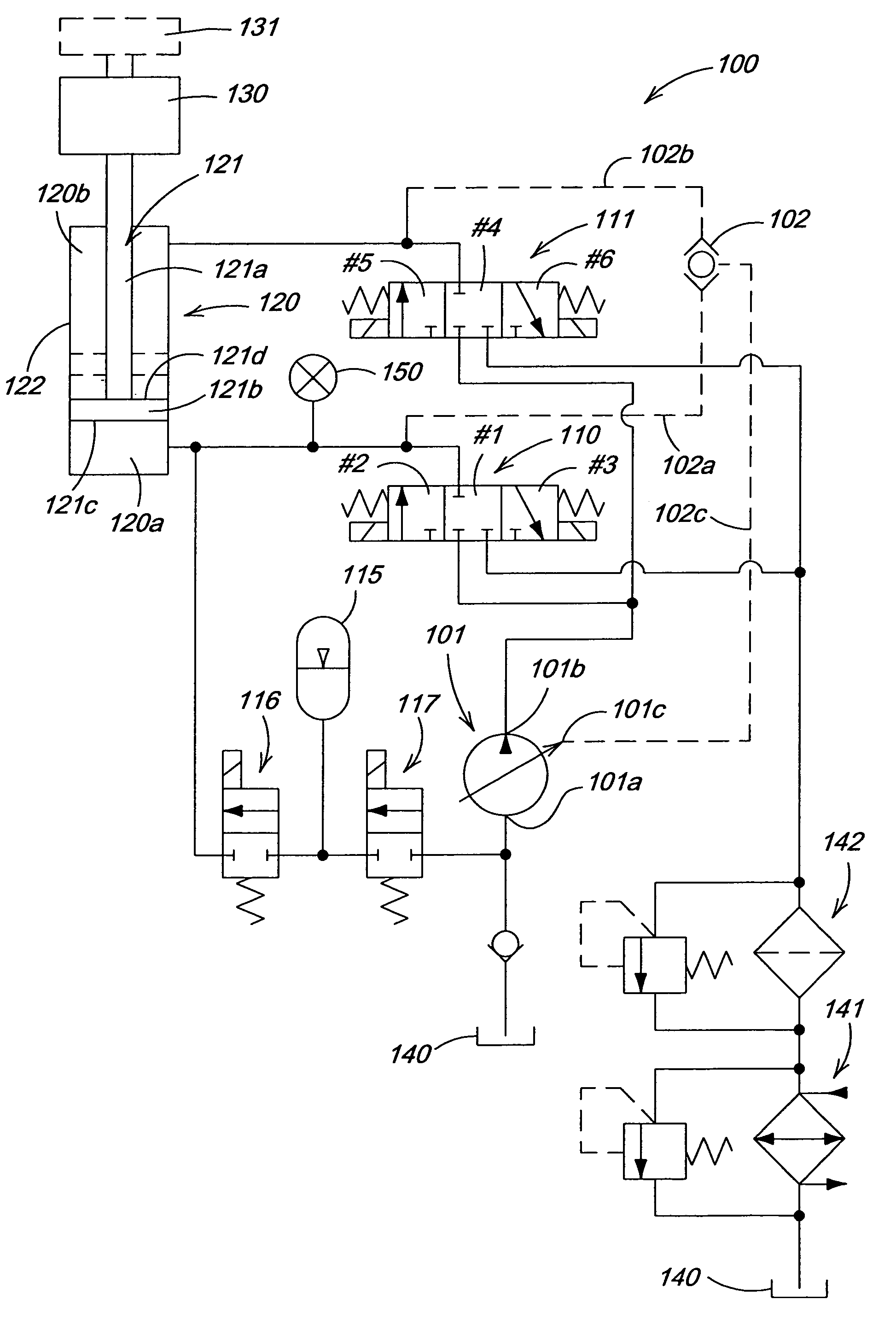
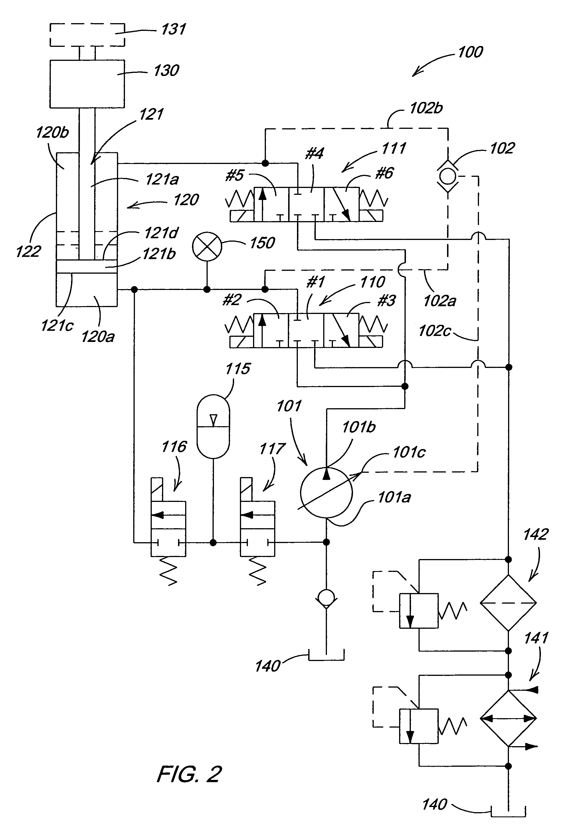
[0011]FIG. 2 illustrates a hydraulic circuit 100...


PUM


Abstract

Hydraulic circuits used to manipulate tools in, for example construction equipment, uses less power for a retraction of a hydraulic cylinder than for an extension of that cylinder. Provided is a hydraulic circuit that uses the stored energy from the low energy phase to lower the energy load on the hydraulic pump during the high energy phase. Energy from the hydraulic pump is increased during the low energy phase to increase the amount of stored hydraulic energy. The increased amount of stored energy is then used to intensify or add to the energy generated by the hydraulic pump for the high energy phase.

Description

FIELD OF THE INVENTION[0001]The invention relates to an energy recovery circuit for a hydraulic apparatus of a work vehicle such as a loader, a backhoe or the like.BACKGROUND OF THE INVENTION[0002]In modern work vehicles, hydraulic circuits are used to power the hydraulic cylinders that manipulate work implements. Such systems may use pumps of the variable displacement type which control the flow rate of hydraulic fluid via manipulation of their displacement volumes. A displacement control valve is used to determine the direction of fluid flow to accomplish the desired work, i.e., for example, to positively extend or retract a double acting hydraulic cylinder. The displacement control valve is also used to allow free flow of fluid so as to minimize pressure generated, i.e., to enable floating; an operating mode in which an implement rests on and follows the contours of the earth as the work vehicle is propelled along the ground.[0003]When a hydraulic cylinder is used to manipulate a...

Claims


Application Information

Patent Timeline
Patent Type & Authority Patents(United States)
IPC IPC(8): F16D31/02
CPCE02F9/2217F15B1/024F15B21/14F15B2211/20523F15B2211/20546F15B2211/212F15B2211/6054F15B2211/7053F15B2211/88
Inventor CHERNEY, MARK JOHNRADKE, DANIEL DEAN
Owner DEERE & CO
Learn More