Eureka AIR delivers breakthrough ideas for toughest innovation challenges, trusted by R&D personnel around the world.

Hermetically sealed electronics arrangement and approach

a technology of electronic arrangement and approach, applied in the field of electromechanical equipment, can solve the problems of damage to components, many types of electronic and electromechanical equipment are susceptible to corrosion and damage, and can be damaged, so as to reduce the magnetic spacing of disk drives, prevent moisture from reaching portions, and eliminate the effect of head and disk corrosion

Inactive Publication Date: 2006-10-17
HITACHI GLOBAL STORAGE TECH NETHERLANDS BV
View PDF24 Cites 61 Cited by
  • Summary
  • Abstract
  • Description
  • Claims
  • Application Information

AI Technical Summary

Benefits of technology

[0021]In one embodiment according to the present invention, a hermetic sealing approach is implemented with electronic or electromechanical equipment, such as disk drives, that is susceptible to corrosion. The equipment is hermetically sealed in a low-humidity environment, thereby preventing moisture from reaching portions of the equipment that are susceptible to corrosion. With this approach, the corrosion of heads and disks can be reduced and / or eliminated, which allows for the thinning or elimination of protective overcoats on the head and disk. In this regard, the magnetic spacing on disk drives can be reduced independently from overcoat limitations. Moreover, track density, spindle rates and performance can be increased while decreasing drag turbulence, track mis-registration, fly-height (the height above a spinning disk at which heads float) altitude sensitivity and power consumption.
[0022]In a more particular example embodiment of the present invention, a magnetic storage system including an HDD is hermetically sealed in a low-humidity, low-density gas environment. The heads of the HDD are implemented without any overcoat protection layer, with the disk having an overcoat that is significantly thin (i.e., less than 2 nanometers) while sufficiently protecting data from head-disk impacts.

Problems solved by technology

Many types of electronic and electromechanical equipment are susceptible to corrosion and damage.
In particular, when moisture is present with electronic circuits and devices, corrosion tends to occur.
In addition, during device processing and implementation, damage can occur to components thereof.
One type of equipment that is highly susceptible to corrosion is recording equipment.
The functionality and operation of such equipment has become increasingly important, such that corrosion and other damage can have drastic consequences.
Unfortunately, corrosion often occurs in magnetic disk drives and heads due to the presence of moisture, which acts as a thin-film electrolyte in combination with oxygen and certain contaminants to drive chemical reactions.
Unfortunately, typical overcoats can inhibit the ability to scale the areal density higher because the thickness of the overcoat must be reduced accordingly.
As the overcoat is thinned, it loses its ability to protect the disks and heads from corrosion and damage.
For example, when overcoats are thinned to about two nanometers or less, the head and disk become particularly susceptible to corrosion and damage.
Much of the power dissipated by HDDs is due to drag from air in the HDD enclosure.
Unfortunately, these approaches do not prevent moisture from passing into the enclosures (HDDs) that they seal.
For instance, the solubility of water in polymers is very high, resulting in high permeation rates for polymer seals.
Other approaches to providing desirable sealing are typically difficult to implement and / or expensive.
For instance, canning-type methods involving compressed polymers and complex geometry are not readily applicable to HDD implementations.
Similarly, sealing approaches involving metal gaskets typically involve relatively high compression forces that are not applicable to typical HDDs, which do not exhibit the stiffness or other characteristics for accommodating large compression forces.
Achieving such stiffness or other characteristics for HDDs and other electronic / electro-mechanical equipment would typically involve expensive and bulky enclosures.
The above-discussed issues have presented challenges to the manufacture and implementation of disk drives and other electronics equipment.

Method used


Image

  • Hermetically sealed electronics arrangement and approach
  • Hermetically sealed electronics arrangement and approach
  • Hermetically sealed electronics arrangement and approach

Examples


Embodiment Construction

[0036]In the following description, reference is made to the accompanying drawings which form a part hereof, and in which is shown by way of illustration the specific embodiments in which the invention may be practiced. It is to be understood that other embodiments may be utilized as structural changes may be made without departing from the scope of the present invention.

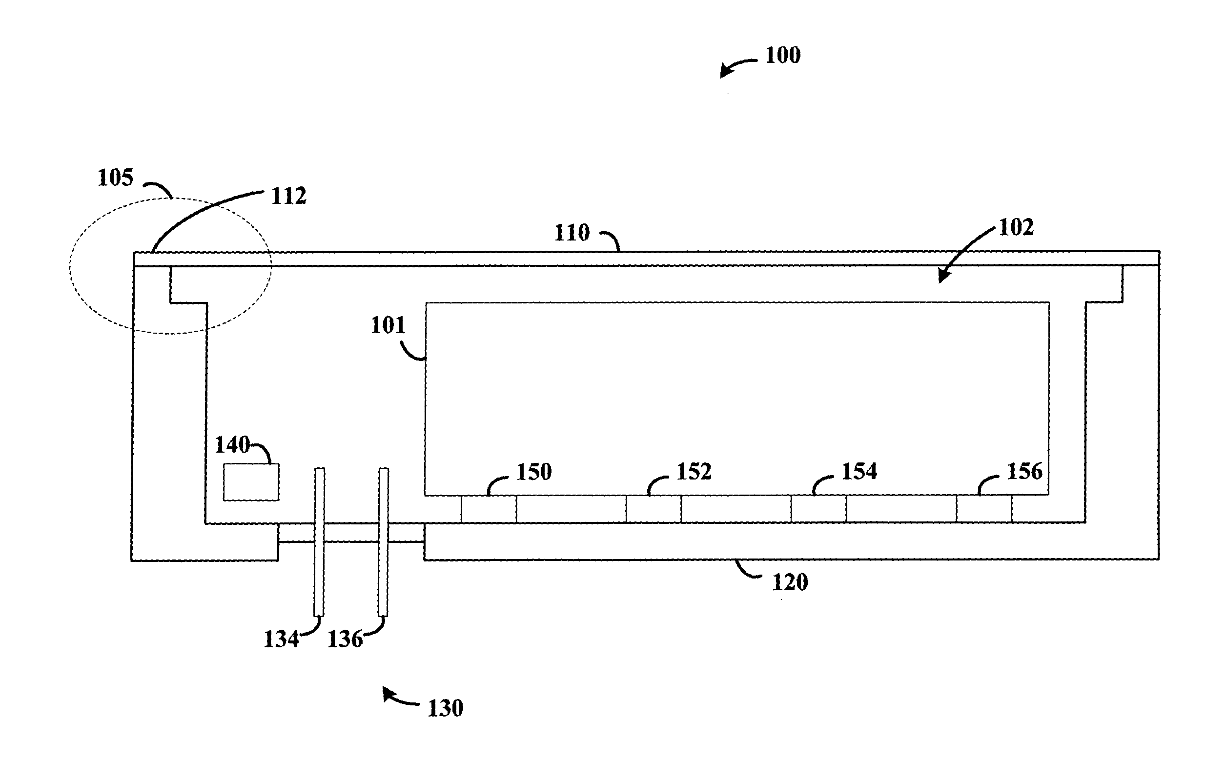
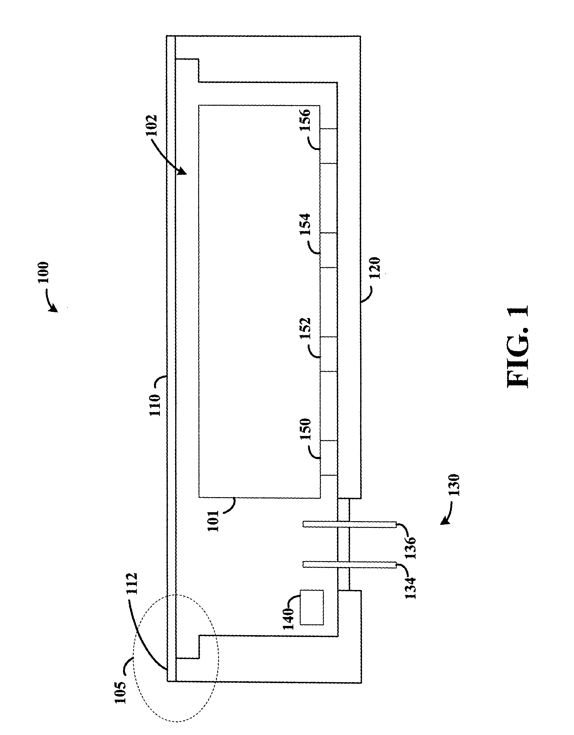
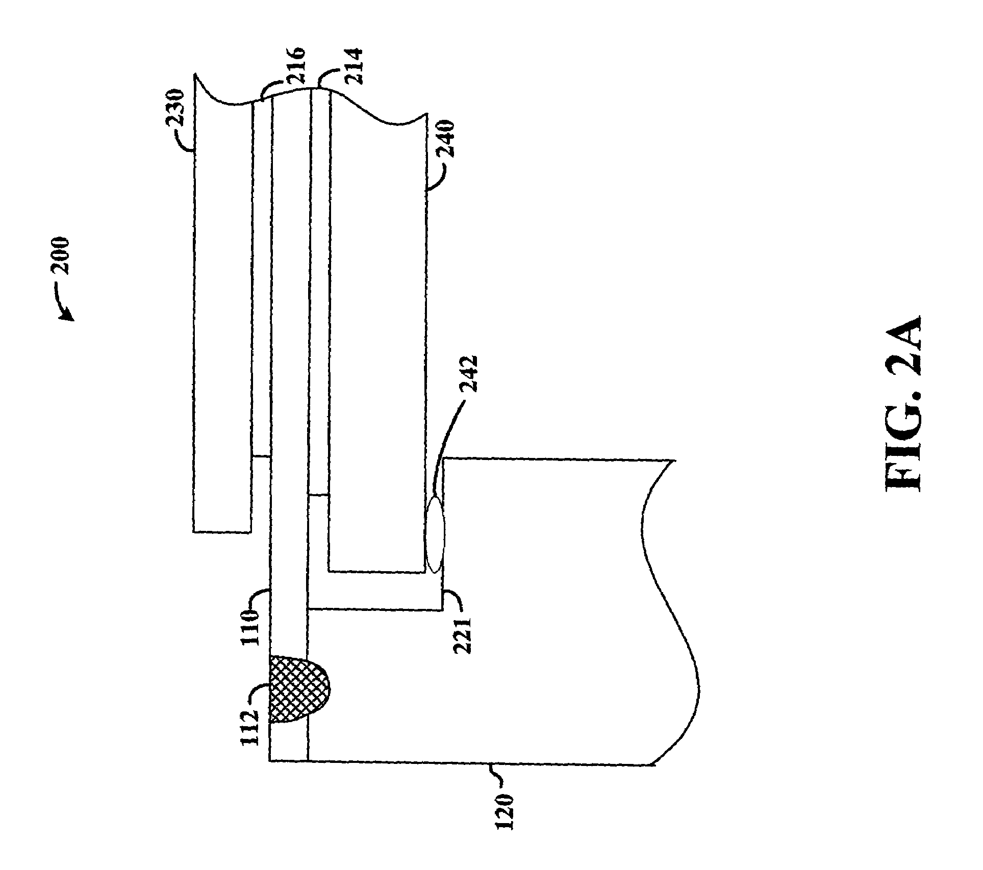
[0037]According to an example embodiment of the present invention, a hermetic sealing approach involves forming a circuit enclosure by welding a metal cover to a cold-forged or die-cast metal base, the cover forming a substantial upper portion of the enclosure. A feedthrough is soldered and / or welded into a small opening in the base and forms a substantially hermetic seal therewith. The feedthrough passes a variety of communication signals and power between circuits sealed in the enclosure and exterior circuits. With this approach, electronic components such as hard disk drives (HDDs) and others are hermetically sea...


PUM

PropertyMeasurementUnit
pressure sensitiveaaaaaaaaaa
pressureaaaaaaaaaa
densityaaaaaaaaaa

Abstract

A hermetic sealing approach involves welding an Aluminum cover onto a low-cost Aluminum housing. According to an example embodiment of the present invention, a metal housing having a base and sidewalls extending upward therefrom is adapted to receive and couple to an HDD arrangement. The metal housing is formed using material and processing (e.g., cold formed or die cast Aluminum) that are relatively inexpensive. A feedthrough arrangement including a plurality of communication pins extends through an opening in the base and is coupled thereto, with the communication pins adapted to pass signals between the inside and the outside of the metal housing. A metal cover is welded to an upper portion of the sidewalls and, with the feedthrough arrangement, hermetically seals the metal housing.

Description

BACKGROUND OF THE INVENTION[0001]1. Field of the Invention[0002]This invention relates in general to electronics and electromechanical equipment, and more particularly to such equipment that is susceptible to corrosion and other damage.[0003]2. Description of Related Art[0004]Many types of electronic and electromechanical equipment are susceptible to corrosion and damage. In particular, when moisture is present with electronic circuits and devices, corrosion tends to occur. In addition, during device processing and implementation, damage can occur to components thereof. The reduction and / or elimination of such corrosion and damage has been important to the operation and longevity of electronic and electromechanical equipment.[0005]One type of equipment that is highly susceptible to corrosion is recording equipment. The functionality and operation of such equipment has become increasingly important, such that corrosion and other damage can have drastic consequences. For example, magn...

Claims


Application Information

Patent Timeline
Patent Type & Authority Patents(United States)
IPC IPC(8): G11B33/14
CPCG11B33/1466H01B17/305
Inventor ALBRECHT, DAVIDSTIPE, BARRYSTRAND, TIMOTHY C.
Owner HITACHI GLOBAL STORAGE TECH NETHERLANDS BV
Why Eureka
Eureka Blog
Learn More