
Transmission mode terahertz computed tomography

a computed tomography and transmission mode technology, applied in the field of terahertz time domain spectroscopy, can solve the problems of excluding the possibility of spectroscopic analysis, restricting the applicability of tomographic techniques, and not meeting the short wave limit of thz wav

Inactive Publication Date: 2006-10-10
RENESSELAER POLYTECHNIC INST
View PDF11 Cites 58 Cited by
  • Summary
  • Abstract
  • Description
  • Claims
  • Application Information

AI Technical Summary

Benefits of technology

This approach enables the construction of high-resolution three-dimensional images with improved pixel density, overcoming the resolution limitations of traditional THz-CT systems by effectively applying X-ray CT algorithms to THz data, resulting in detailed imaging capabilities comparable to X-ray CT technology.

Problems solved by technology

Such assumptions restrict the applicability of the tomographic technique and exclude the possibility of spectroscopic analysis.
Although computed tomography is well known in X-ray radiographic imaging, a serious problem in reconstructing an image using THz computed tomography is that the THz wave does not satisfy the short wave limit as the X-ray satisfies in X-ray computed tomography.
This implies that the resulting image of the target only contains 30×30 pixels—an inadequate resolution.

Method used


Image

  • Transmission mode terahertz computed tomography
  • Transmission mode terahertz computed tomography
  • Transmission mode terahertz computed tomography

Examples


Embodiment Construction

[0050]The invention will next be described with reference to the figures in which the same numbers are used to indicate the same elements in all figures. The figures are used to illustrate the invention and avoid elements not needed to explain the invention, so as not to unduly clutter and complicate the illustrations.

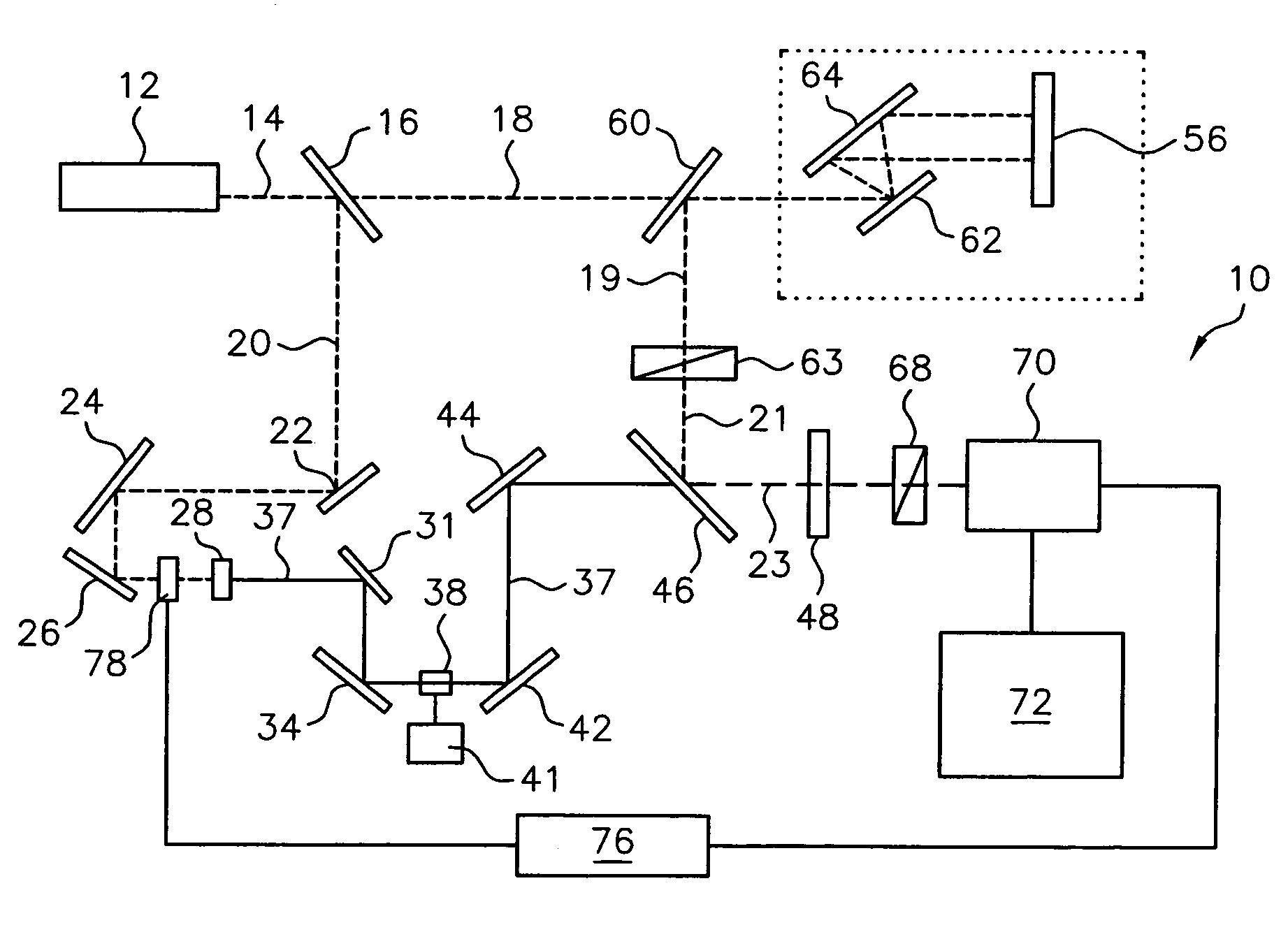
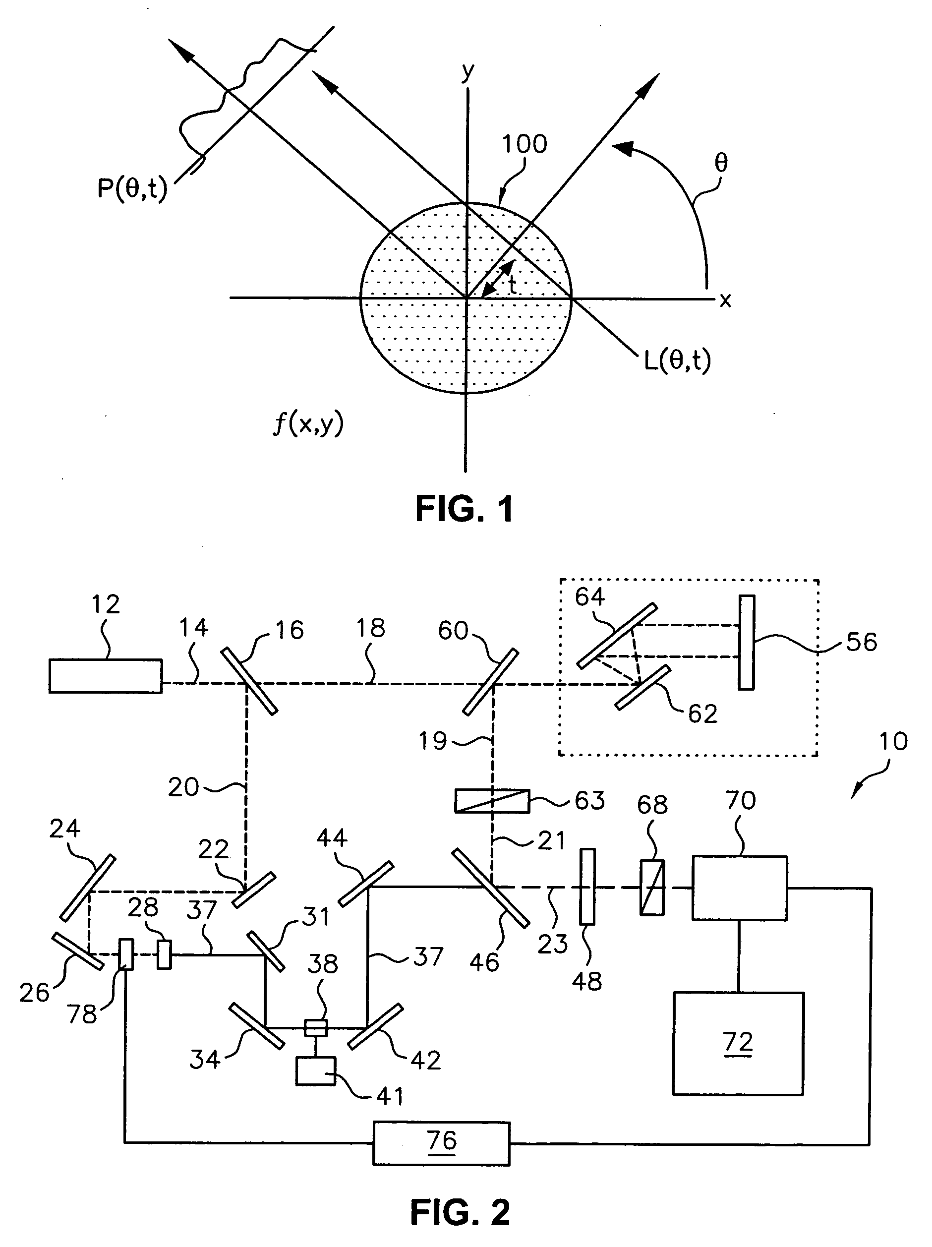
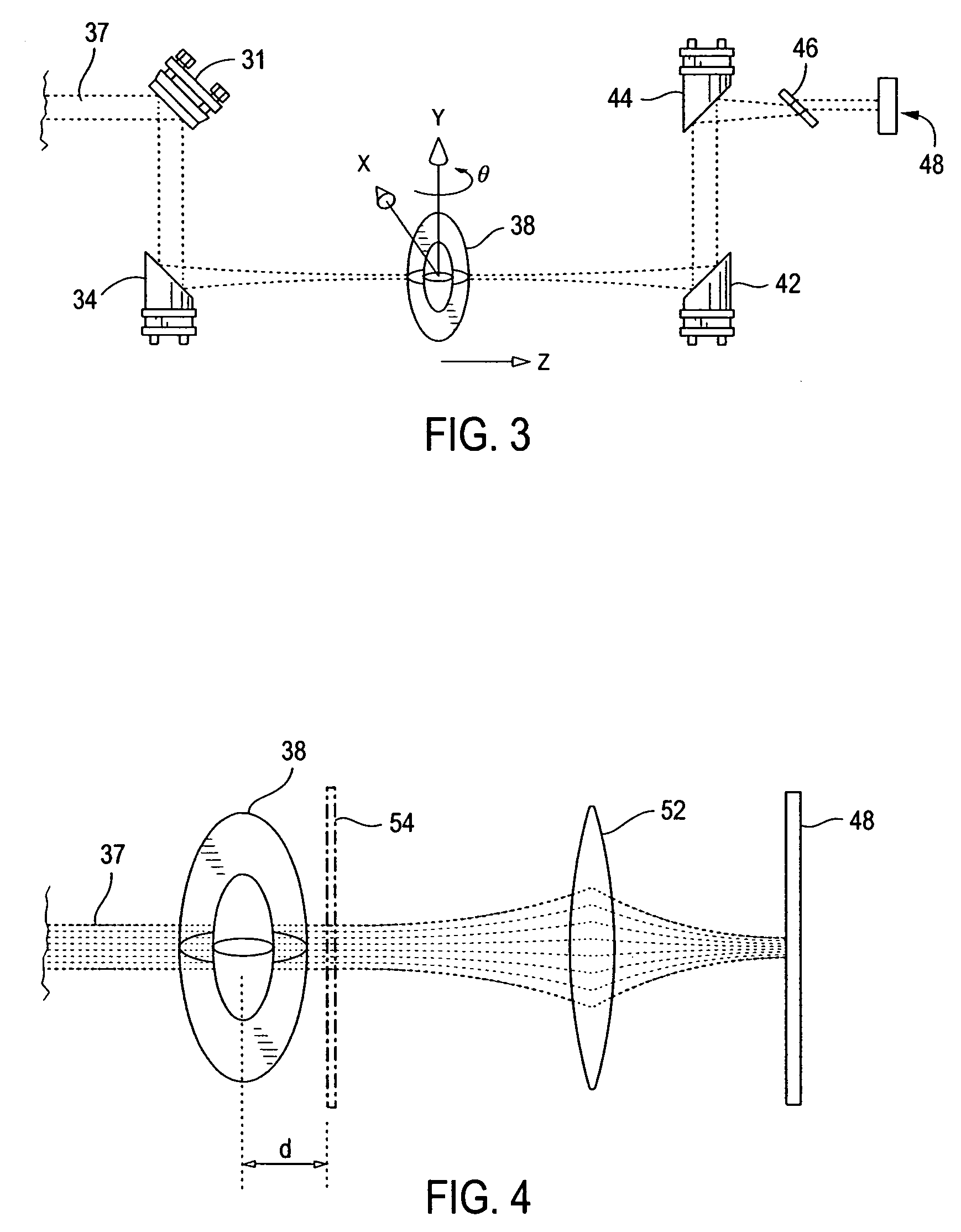
[0051]Computed tomography is conceptually similar to X-ray tomography in that both imaging processes obtain imaging data as data representing a series of individual slices taken through an object. As mentioned above, however, although CT imaging is well known in X-ray radiography, the wave differences between X-ray radiation and THz radiation are sufficiently significant so that X-ray CT technology may not be simply applied to THZ-CT applications. The present invention overcomes the limitations due to the wave differences between THz radiation and X-ray radiation and describes a practical THz-CT system that successfully uses X-ray CT algorithms for image capture and re...


PUM

PropertyMeasurementUnit
angleaaaaaaaaaa
beam diffraction angleaaaaaaaaaa
sizeaaaaaaaaaa

Abstract

A method of obtaining a series of images of a three-dimensional object by transmitting pulsed terahertz (THz) radiation through the entire object from a plurality of angles, optically detecting changes in the transmitted THz radiation using pulsed laser radiation, and constructing a plurality of imaged slices of the three-dimensional object using the detected changes in the transmitted THz radiation. The THz radiation is transmitted through the object as a scanning spot. The object is placed within the Rayleigh range of the focused THz beam and a focusing system is used to transfer the imaging plane from adjacent the object to a desired distance away from the object. A related system is also disclosed.

Description

[0001]This application is a continuation-in-part application of PCT International Application Number PCT US02 / 36279 filed on Nov. 13, 2002 designating the United States, the entire contents of which are incorporated in this document by reference.[0002]The U.S. Government has a paid-up license in this invention and the right in limited circumstances to require the patent owner to license others on reasonable terms as provided for by the terms of Contract No. DE-FG07-98ER6270 awarded by the Department of Energy and Contract Nos. DAAD-19-99-1-0333 and DAAD-1999C0045 awarded by the U.S. Army.FIELD OF THE INVENTION[0003]The invention relates generally to terahertz time domain spectroscopy (THz-TDS) and, more particularly, to systems and associated methods for high resolution terahertz computed tomography (THz-CT).BACKGROUND OF THE INVENTION[0004]The term “terahertz” (THz), originally used by sub-millimeter spectroscopists to describe spectral lines with frequencies in the trillions of he...

Claims


Application Information

Patent Timeline
Patent Type & Authority Patents(United States)
IPC IPC(8): G01J5/28G01N21/17G01N21/63G01R31/308H01L31/00G01N21/35
CPCG01N21/3581
Inventor FERGUSON, BRADLEY STUARTWANG, SHAOHONGZHANG, XI-CHENG
Owner RENESSELAER POLYTECHNIC INST
Learn More