
Touch pad device for portable computer

a portable computer and touch pad technology, applied in the field of portable computers, can solve the problems of long assembly process, difficult management, large number of components, etc., and achieve the effects of simple assembly process, low manufacturing cost, and reduced number of components

Inactive Publication Date: 2006-10-10
LG ELECTRONICS INC
View PDF10 Cites 39 Cited by
  • Summary
  • Abstract
  • Description
  • Claims
  • Application Information

AI Technical Summary

Benefits of technology

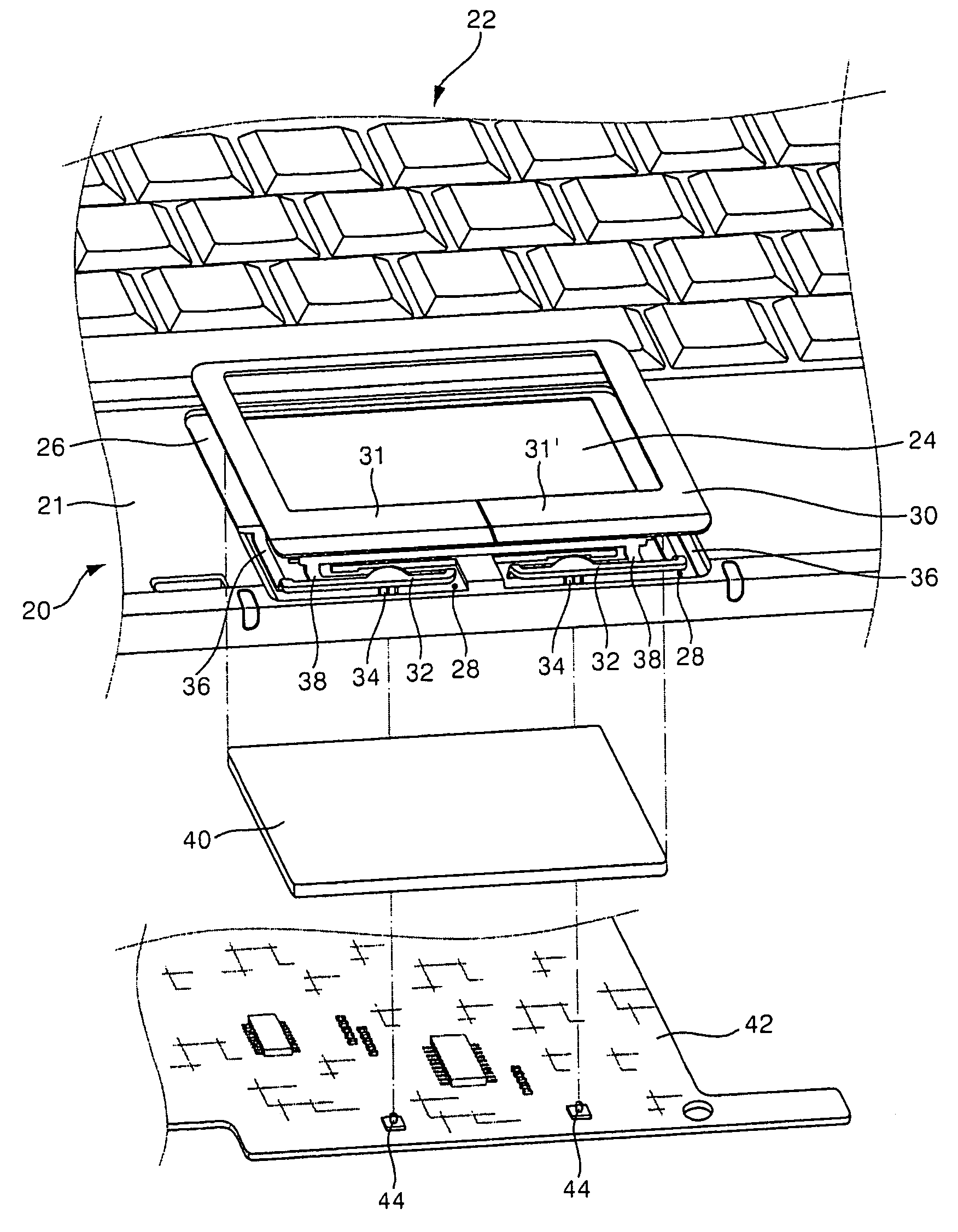
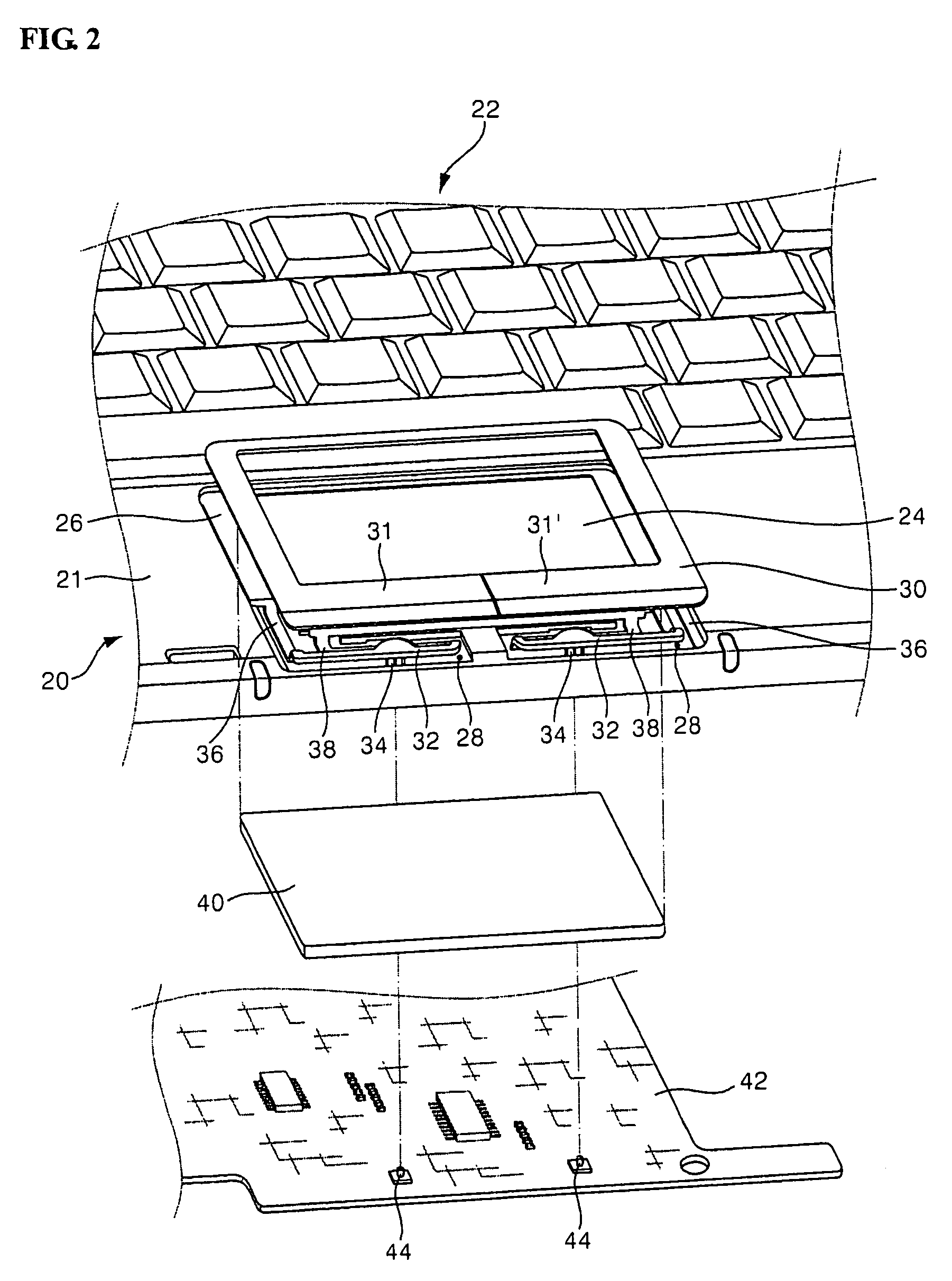
The present invention provides a touch pad device for a portable computer with a small number of components. The device includes a key deck, a touch region on the key deck, penetration portions, push buttons, a touch pad, a cover button, and a board with switches. The push buttons are integrally formed with the key deck and can deform elastically inside the penetration portions. The device is advantageous in that it has a minimized number of components, a simple assembly process, and a low manufacturing cost. The positional relationship of the push buttons is always maintained correctly, improving the operation reliability of the touch pad device.

Problems solved by technology

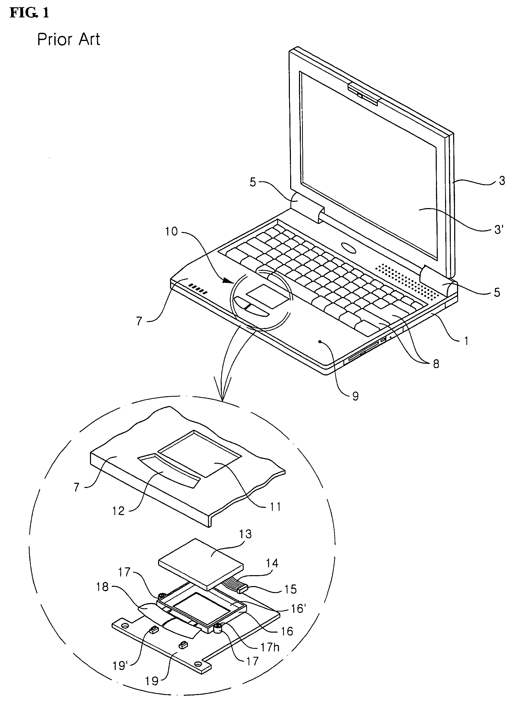
However, conventional touch pad devices 10, constructed as above, have a problem in that they have a large number of components, including the touch pad 13, touch pad housing 16, buttons 18, and pad board 19.
This makes it difficult to manage them and lengthens the assembly process.
This means that the touch pad device 10 may fail to function properly.

Method used


Image

  • Touch pad device for portable computer
  • Touch pad device for portable computer
  • Touch pad device for portable computer

Examples


Embodiment Construction

[0030]Hereinafter, a preferred embodiment of the present invention will be described with reference to the accompanying drawings. In the following description and drawings, the same reference numerals are used to designate the same or similar components, and so repetition of the description on the same or similar components will be omitted.

[0031]FIG. 2 is an exploded perspective view showing the construction of a touch pad device for a portable computer according to a preferred embodiment of the present invention. FIG. 3 is a perspective view showing a key deck, from above, according to an embodiment of the present invention. FIG. 4 is a perspective view showing a key deck, from below, according to an embodiment of the present invention.

[0032]As shown in the drawings, the key deck 20 forms the exterior of the outer surface of the main unit of the portable computer. Although the key deck 20 generally forms the exterior of the upper surface of the main unit, it may also form the front...


PUM


Abstract

A touch pad device for a portable computer includes a key deck (20); a touch region (24) formed on a portion of the key deck (20); penetration portions (28) extending through the key deck (20) while being adjacent to the touch region (24); push buttons (32) integrally formed with the key deck (20) while being able to deform elastically inside the penetration portions (28); a touch pad (40) formed on a lower surface of the key deck (20) in a position corresponding to the touch region (24) for information input; a cover button (30) mounted on an upper surface of the key deck (20) to cover at least the push buttons (32) and the penetration portions (28), the cover button (30) having first and second button units (31) and (31′) able to deform elastically and compress the push buttons (32); and a board (42) having switches (44) toggled on / off by pushing the button units (31) and (31′).

Description

BACKGROUND OF THE INVENTION[0001]1. Field of the Invention[0002]The present invention relates to a portable computer, and more particularly to a touch pad device used as an input device in a portable computer.[0003]2. Description of the Prior Art[0004]As generally known in the art, portable computers (e.g. laptop computers) are provided with a touch pad device or pointing stick, which is used as a pointing device instead of a mouse when the computers are carried. FIG. 1 shows a portable computer equipped with a touch pad device according to the prior art.[0005]As shown, the portable computer generally includes a main unit 1 and a display unit 3. Both ends of the display unit 3 are connected to the rear end of the main unit 1 by hinge units 5 so that the display unit 3 can be folded on the upper surface of the main unit 1 or unfolded at a predetermined angle as shown in the drawing. The display unit 3 has a display screen 3′, such as a liquid crystal panel.[0006]The main unit 1 has a...

Claims


Application Information

Patent Timeline
Patent Type & Authority Patents(United States)
IPC IPC(8): H01H9/00
CPCG06F1/1616G06F1/169G06F3/03547G06F2203/04103
Inventor SUN, YOU MYOUNG
Owner LG ELECTRONICS INC
Learn More