
Cylinder carrying and chocking apparatus and method

a technology for cylinders and supports, applied in the direction of traveling carriers, hoisting equipment, lifting devices, etc., can solve the problems of personal injury or damage to bottles, the ability to carry scuba tanks, and the inability to comfortably and not for long distances, so as to reduce the potential for rolling around, prevent the effect of rolling the tank and inhibit the effect of rolling

Inactive Publication Date: 2006-10-10
MERTZ JR KENNETH A
View PDF16 Cites 13 Cited by
  • Summary
  • Abstract
  • Description
  • Claims
  • Application Information

AI Technical Summary

Benefits of technology

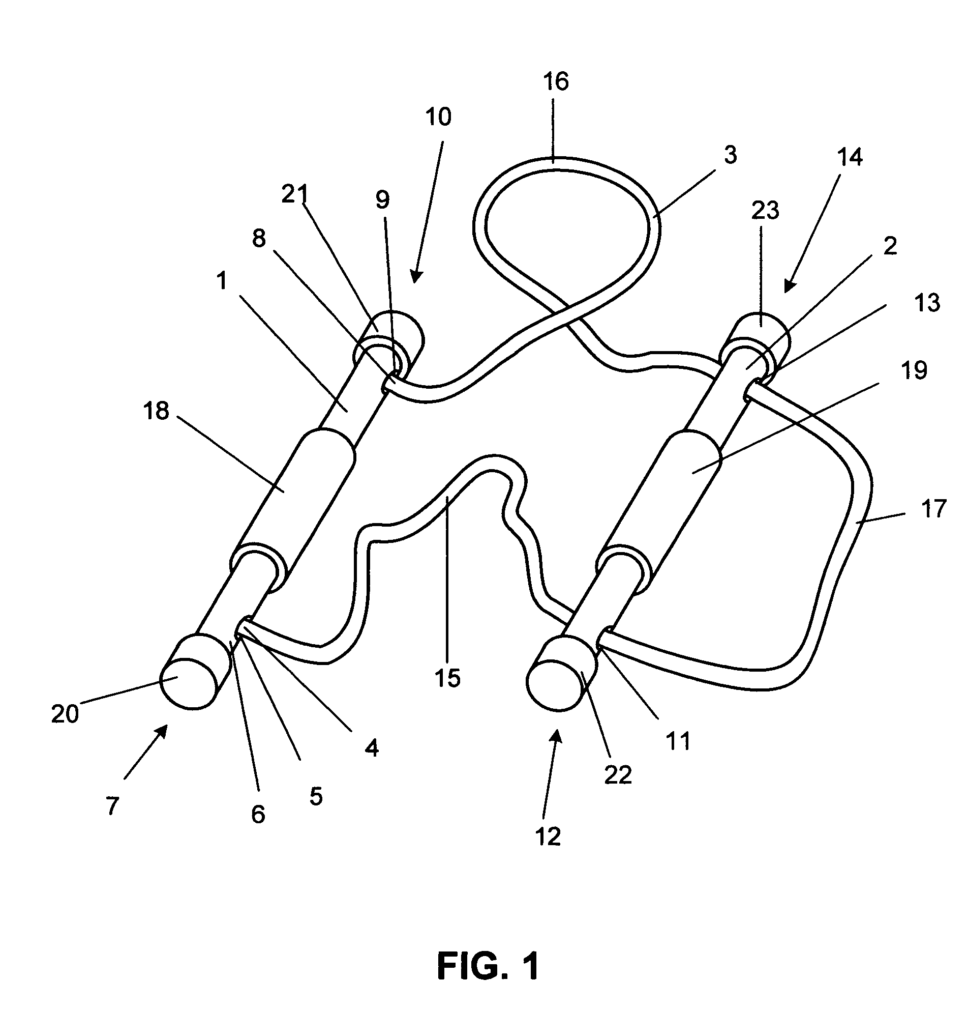
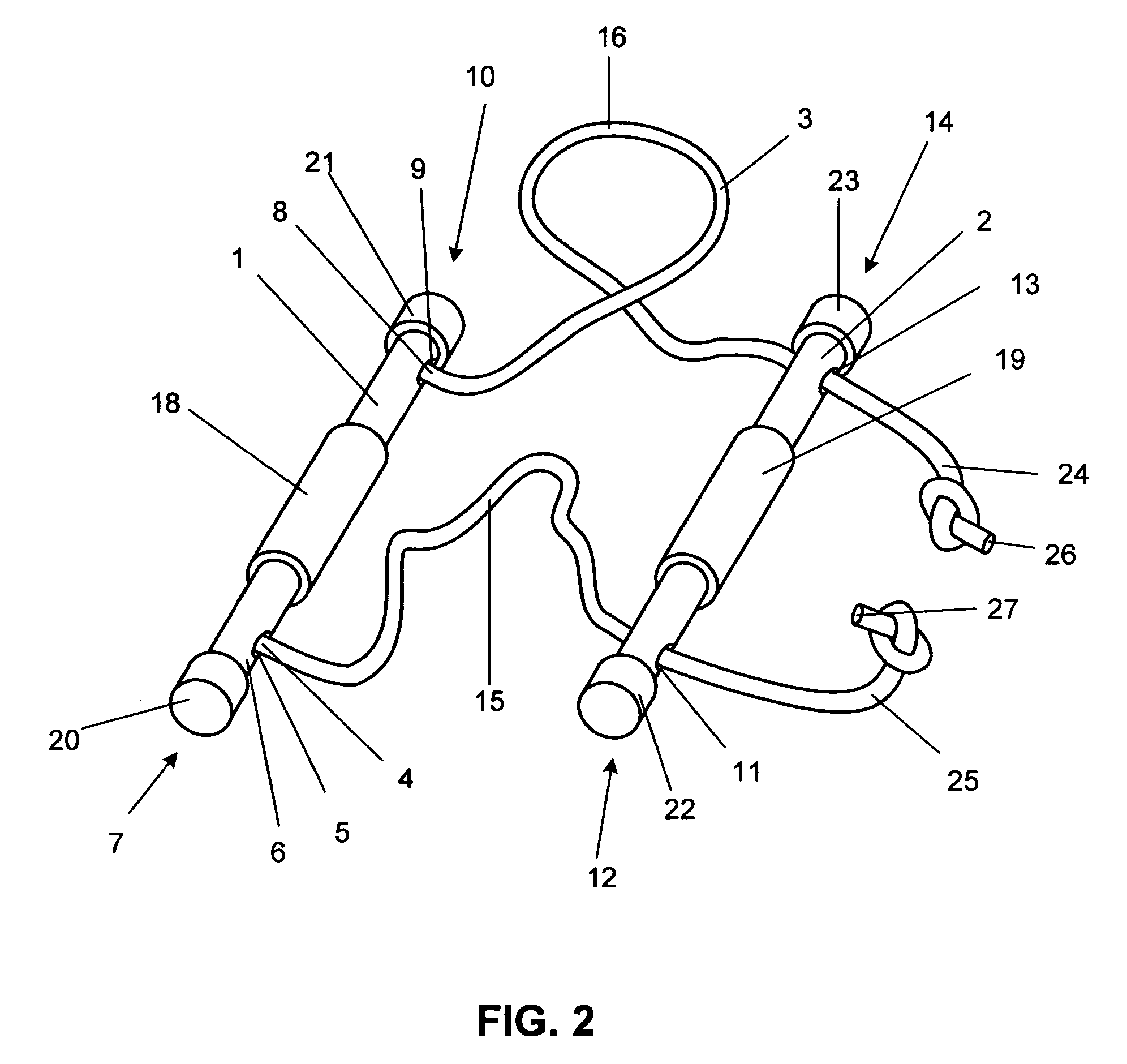
[0006]The present invention comprises a rope and two rigid elongate handles, the rope being fixed to one end of the first handle, threaded through first one end and then the other end of the second handle, and finally fixed to the other end of the first handle. The rope thereby forms a loop with two sides of the rope loop running through the second handle. This allows the second handle to be slid along the two sides of the rope to increase or decrease the distance between the handles. To use the device to carry a scuba tank, the rope and handles are first laid on a flat surface to form a rectangle with the handles being the right and left sides of the rectangle and the two sides of the rope loop being the top and bottom. The scuba tank is placed on the rope (parallel to the handles) and the handles are lifted and brought together, causing the two sides of the rope to encircle the tank. The second handle is then inserted between the two sides of the rope coming from the first handle (or vice versa) and lifted to bring the scuba tank off the surface.
[0007]The tank can be transported in a vehicle with reduced potential for rolling around in the vehicle by lowering the tank (held by the invention) into a flat space in a vehicle (such as a trunk), separating the handles, and laying them out on either side of the tank. The fixed handle is placed against the tank, and the slidable handle is drawn up against the tank by pulling the rope outward from the tank through the holes in that handle. Frictional engagement between the handles and the tank prevents rolling of the tank on the surface. Another embodiment of the invention provides a portion of each handle with at least one flat side so as to further inhibit rolling.
[0008]The handles are coated with resilient friction-enhancing material to provide a more comfortable grip while it is carried and to engage the wall of the tank to inhibit roll when it is supported by a flat surface.
[0009]It is an object of this invention to provide a simple and inexpensive method for safely hand-carrying a scuba tank or other gas bottle with one hand. Another object of the invention is to provide means to prevent such tank from rolling on a flat surface, such as within a moving vehicle.

Problems solved by technology

Only small ones such as scuba tanks can be carried by hand at all without some kind of aid to hand carriage, and even then not comfortably and not for long distances.
Their shape, generally cylindrical, flat or dished at one end and rounded with an axially-installed valve at the other, makes them ungainly; many users handle them by the valve or regulator.
This is not recommended, because these parts are not shaped for secure grasp and allow some chance for dropping the bottle.
If the bottle is dropped, personal injury or damage to the bottle can occur; in the worst case, catastrophic failure of the valve stem could occur with explosive release of the compressed gas.
The drawback to these devices is that the handles are not adjustable and they do not prevent the bottle from rolling around in a vehicle.

Method used


Image

  • Cylinder carrying and chocking apparatus and method
  • Cylinder carrying and chocking apparatus and method
  • Cylinder carrying and chocking apparatus and method

Examples


first embodiment

[0020]FIG. 3 is a perspective view of the first embodiment carrying a scuba tank 201. The tank 201 is shown with a typical bottom cap 202 and valve stem 203, which are not part of the invention. To carry the tank, the near portion 15 and the far portion 16 of the rope 3 are wrapped around the tank 201, and sliding handle 2 is inserted between the near and far portions 15 and 16. When sliding handle 2 is pulled upward by the hand of a user, represented by arrow A, grasping sliding resilient grip 19, sliding handle 2 slides upward on rope 3 until it is stopped by the median portion 17 of the rope 3. Farther upward motion by the user lifts everything.

[0021]It is evident that the invention will function equally well if fixed handle 1 instead of sliding handle 2 is inserted between the near and far rope portions 15 and 16, while still lifting sliding handle 2. This would place rope bights 204 and 205 outside of rope portions 15 and 16, respectively, instead of inside as shown. It is also...

third embodiment

[0024]FIG. 6 is a perspective view of the invention. In this embodiment, angular blocks 501, 502, 503, and 504 replace end caps 20–23 in the earlier drawings. the flat sides of the angular blocks provide an added measure of roll prevention if desired.

[0025]FIG. 7 is an end view of the third embodiment showing tank 201 chocked by angular blocks 501 and 503.


PUM


Abstract

A carrier for a scuba tank or other cylindrical bottle comprises two cylindrical handles connected by a looped rope, the rope passing slidably through one of the handles. The scuba tank is supported by the ropes and carried by one handle looped through the rope. The handles may also be used to chock the tank against rolling in a vehicle, by placing the tank next to one handle and sliding the other handle up against the tank.

Description

BACKGROUND OF INVENTION[0001]This invention is in the field of article carriers and supports, more specifically in the field of carriers and supports for compressed gas bottles, and more specifically still in the field of hand carriers for scuba tanks. The invention also pertains to the secure transport of compressed gas bottles in vehicles, and more specifically to the transport of scuba tanks to and from dive sites by vehicle and by hand. Although this invention can be used on a variety of cylinders, for simplicity the terms “scuba tank” or “tank” will generally be used herein to represent the item being carried by the invention.[0002]Because they are generally comprised of thick-walled metal, compressed gas bottles are relatively heavy objects to carry by hand. Only small ones such as scuba tanks can be carried by hand at all without some kind of aid to hand carriage, and even then not comfortably and not for long distances. Their shape, generally cylindrical, flat or dished at o...

Claims


Application Information

Patent Timeline
IPC IPC(8): B65G7/12
CPCB65G7/12
Inventor MERTZ, JR., KENNETH A.
Owner MERTZ JR KENNETH A
Learn More