Al technical title is built by PatSnap Al team. It summarizes the technical point description of the patent document.
A hydraulic prop and dust-proof technology, which is applied in the direction of props/supports, mining equipment, earthwork drilling, etc., can solve problems such as hydraulic prop blockage, hydraulic prop rolling, hydraulic prop damage, etc., to reduce the failure rate and the probability of rolling , the effect of improving stability
Active Publication Date: 2019-12-31
山东博士乐液压有限公司
View PDF6 Cites 0 Cited by
Summary
Abstract
Description
Claims
Application Information
AI Technical Summary
This helps you quickly interpret patents by identifying the three key elements:
Problems solved by technology
Method used
Benefits of technology
Problems solved by technology
[0003] The valve nozzle of the hydraulic prop in the prior art is exposed to the air for a long time, so that the coal powder in the coal mine is easy to accumulate inside the valve nozzle. During the liquid injection process of the hydraulic prop, the coal powder is easily washed into the interior of the hydraulic prop. It is easy to cause blockage inside the hydraulic prop. Not only that, the shape of the hydraulic prop in the prior art is cylindrical. When the hydraulic prop is square on the ground with a slope, the hydraulic prop is prone to rolling. If the hydraulic prop collides with other objects , causing the hydraulic prop to be easily damaged
Method used
Image
Click on the blue label to locate the original text in one second.
Reading with bidirectional positioning of images and text.
Examples
Embodiment Construction
[0024] The present invention is described in further detail now in conjunction with accompanying drawing. These drawings are all simplified schematic diagrams, which only illustrate the basic structure of the present invention in a schematic manner, so they only show the configurations related to the present invention.
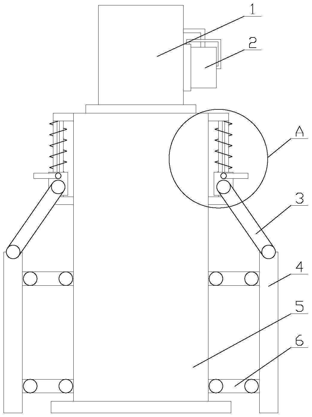
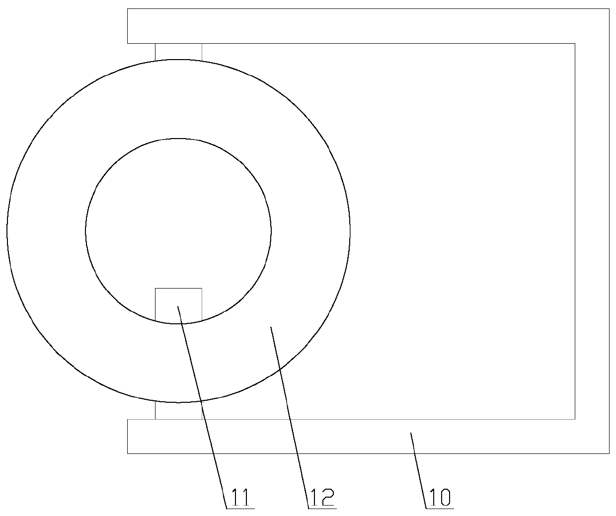
[0025] like figure 1 As shown, a stable dust-proof hydraulic prop includes a live column 1, a column body 5 and a valve nozzle 18. The live column 1 is connected to the column body 5, and the valve nozzle 18 is installed on the live column 1. It also includes a dust-proof mechanism and two support mechanisms, the dust-proof mechanism is arranged on the valve nozzle 18, the two support mechanisms are arranged symmetrically about the axis of the column body 5, and both support mechanisms are arranged on the column body 5;
[0026] Under the support of the support mechanism, the probability of hydraulic prop rolling is reduced, and the stability of hydraulic pro...
PUM
Abstract
The invention relates to a stably-placed dustproof hydraulic prop. The stably-placed dustproof hydraulic prop comprises a movable prop, a prop body and a valve nozzle, the movable prop is connected with the prop body, the valve nozzle is installed on the movable prop, a dustproof mechanism and two supporting mechanisms are further included, the supporting mechanisms comprise sliding rods, positioning ropes, springs, moving casing pipes, first connecting rods, second connecting rods and two third connecting rods, and the dustproof mechanism comprises a dustproof cover, a first annular air bag,a second annular air bag, a supporting pipe, a gas pipe, a limiting plate and a piston block. According to the stably-placed dustproof hydraulic prop, under the supporting effect of the supporting mechanism, the probability of rolling of the hydraulic prop is decreased, the stability of placement of the hydraulic prop is improved, through the protective effect of the dustproof mechanism, the probability of dust entering the valve nozzle is decreased, and the failure rate of the hydraulic prop is decreased; and compared with an existing dustproof mechanism, according to the dustproof mechanism,when the dustproof cover is taken down, the inner wall of the valve nozzle can further be cleaned, and the amount of the dust entering the inner part of the hydraulic prop is decreased.
Description
technical field [0001] The invention relates to the field of hydraulic equipment, in particular to a stable dust-proof hydraulic prop. Background technique [0002] The hydraulic prop refers to a single retractable prop that uses liquid pressure to generate working resistance and realize lifting and unloading. The hydraulic prop is mainly divided into suspension type, double telescopic suspension type, DN inner injection type and glass fiber reinforced plastic hydraulic prop. The hydraulic prop is made of It is composed of cylinder, live column, valve and other parts, among which the three-purpose valve is the heart of the external injection hydraulic prop, which is composed of a one-way valve, an unloading valve and a safety valve king. The valve is used for unloading and returning the hydraulic prop to the post, and the safety valve ensures that the hydraulic prop has constant resistance characteristics. [0003] The valve nozzle of the hydraulic prop in the prior art is ...
Claims
Application Information
Patent Timeline
Application Date:The date an application was filed.
Publication Date:The date a patent or application was officially published.
First Publication Date:The earliest publication date of a patent with the same application number.
Issue Date:Publication date of the patent grant document.
PCT Entry Date:The Entry date of PCT National Phase.
Estimated Expiry Date:The statutory expiry date of a patent right according to the Patent Law, and it is the longest term of protection that the patent right can achieve without the termination of the patent right due to other reasons(Term extension factor has been taken into account ).
Invalid Date:Actual expiry date is based on effective date or publication date of legal transaction data of invalid patent.