Vehicle safety device and using method
An automobile safety device and vehicle panel technology, which is applied to motor vehicles, transportation and packaging, and vehicles used for freight transportation, etc. It can solve problems such as large potential energy of steel coils, broken connection positions of steel cables and vehicle panels, etc., and achieves ease of jumping. Power, avoid fixed failure, avoid roll effect
- Summary
- Abstract
- Description
- Claims
- Application Information
AI Technical Summary
Problems solved by technology
Method used
Image


Examples
Embodiment 1
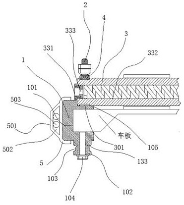
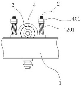
[0045] An automobile safety device, comprising clips 1 fixedly installed on the left and right sides of the vehicle panel, the clip 1 has a bayonet 101 for being inserted into the vehicle panel, and the bottom of the clip 1 is provided with a pillar 102, The outer wall of the column 102 is provided with a fixing groove 103, and a threaded hole is provided at the bottom of the column 102, and the threaded hole penetrates upwards to the bayonet 101, and a screw 104 is fitted in the threaded hole, The screw 104 is screwed up against the vehicle board; a plurality of arc-shaped grooves 105 are arranged on the top of the clip 1, and the end of the groove 105 away from the vehicle board is closed, and the other end is penetrated; The top of the bar 1 is located at the front and rear sides of each of the grooves 105. A guide post 2 is provided; a stop bar 3 is installed between the left and right two clip bars 1, and the stop bar 3 fits on the In the groove 105; on the upper part of ...
Embodiment 2
[0047] The anti-scratch pad 5 of rubber material is assembled on the end of the clip bar 1 away from the car plate, and the end of the clip bar 1 away from the clip bar 1 is provided with a convex deformation part 501; The main role is to reduce scratch damage during vehicle movement. At the same time, when the steel coil is transported, part of the steel cable is originally in contact with the clips. Due to the high hardness of the clips, the steel cables will be worn. And the anti-scratch pad can be in contact with the wire rope to reduce the wear of the wire rope. At the same time, because the anti-scratch pad is elastic, we can tighten the steel coil when fixing the steel coil through the steel cable. When the steel coil jumps, the steel cable will be pressed into the anti-scratch pad to provide steel There is a certain jumping space, and at the same time, after the jumping disappears, the anti-scratch pad rebounds, and the steel cable is tightened again.
[0048] The in...
Embodiment 3
[0051] The upper end of the fixing groove 103 is provided with a wire clamping groove 133; the wire clamping groove 133 can be clamped into the wire rope 9 to increase the assembly firmness between the wire rope 9 and the wire fixing groove 103.
PUM
 Abstract
Description
Claims
Application Information
 - Generate Ideas
- Intellectual Property
- Life Sciences
- Materials
- Tech Scout
- Unparalleled Data Quality
- Higher Quality Content
- 60% Fewer Hallucinations
Browse by: Latest US Patents, China's latest patents, Technical Efficacy Thesaurus, Application Domain, Technology Topic, Popular Technical Reports.
© 2025 PatSnap. All rights reserved.Legal|Privacy policy|Modern Slavery Act Transparency Statement|Sitemap|About US| Contact US: help@patsnap.com