
Electrodynamic tether

a technology of electrodynamic tethers and tethers, applied in the direction of cosmonautic power supply systems, cosmonautic components, cosmonautic parts, etc., can solve the problems of reducing the effective life of the tether, losing the electrodynamic properties, and bare wire tethers of copper or aluminum, etc., to increase or decrease the orbit of a satellite or power subsystem.

Inactive Publication Date: 2006-10-10
NASA
View PDF18 Cites 13 Cited by
  • Summary
  • Abstract
  • Description
  • Claims
  • Application Information

AI Technical Summary

Benefits of technology

[0009]It is thus an object and intention of this invention to overcome these problems with the prior art devices and provide an electro-dynamic tether that can effectively increase or decrease the orbit of a satellite or power subsystems and charge batteries of a spacecraft. It is a further object to provide a tether that fits within the weight and volume constraints of the existing Small Expendable Deployer Systems (SEDS). The tether must also be strong enough to withstand the forces exerted by deployment and the tether dynamics and further to survive the space environment including atomic oxygen, temperatures and micrometeoroid / orbital debris (M / OD) to accomplish the mission duration of twenty-four hours to twenty-one days.
[0011]In a preferred embodiment, the length of the non-conducting section is preferably 10 km. Such length provides sufficient gravity-gradient tension to both deploy the conductive tether and to stabilize the entire system under action of electro-dynamic thrust force.
[0012]In another embodiment, the conducting section is coated with an atomic oxygen resistant conducting polymer, such as C-COR, made by Triton Systems, Inc. of Chelmsford, Mass. The conducting section of the tether collects electrons from the space plasma. The coating on the conducting section provides good surface conductivity for electron collection and improved surface optical properties for thermal control that prevents the aluminum wire from overheating.
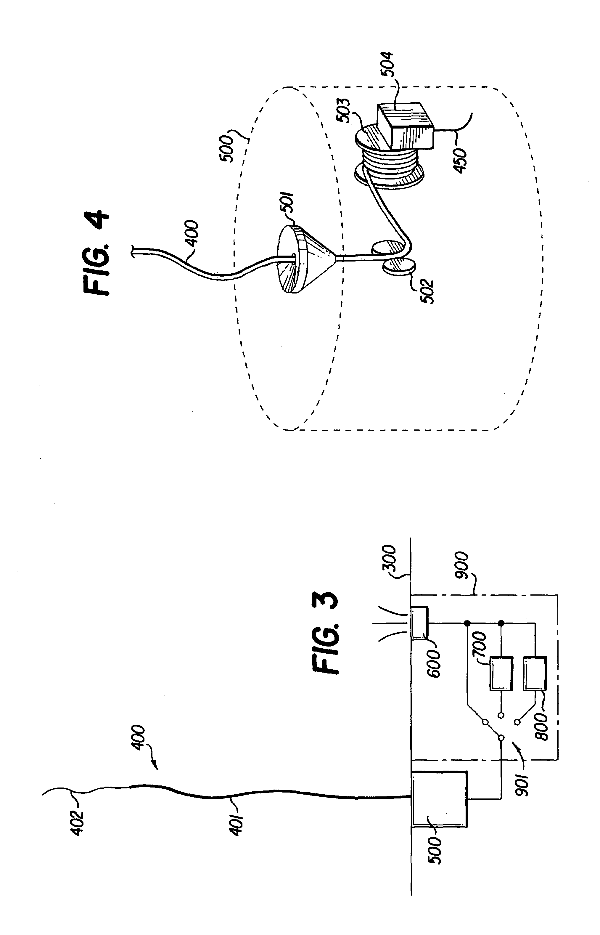
[0013]In a further embodiment, each aluminum wire of the insulating section is over coated with a polyimide and an oxygen resistant, insulating polymer, such as TOR-BP, made by Triton Systems, Inc. of Chelmsford, Mass. The insulating section, which is closest to the spacecraft or satellite, prevents electron re-connection from the plasma contactor to the tether.
[0014]In another embodiment, the aluminum wires of the conducting and insulating sections are wrapped around a braided KEVLAR aramid fiber core. The aramid fiber core provides ample tensile strength as well as improved windability and deployability.
[0015]In a fifth embodiment, the aluminum wires in the conducting section and the insulating section are cold welded together. A cold weld provides strong bond between the wires while not damaging or oxidizing the aluminum.

Problems solved by technology

However, a problem with bare wire plasma contactors is that in an oxygen rich environment of a low Earth orbit, the bare wire tethers of copper or aluminum would quickly oxidize and degrade, losing their electro-dynamic properties.
Such greatly reduces the effective life of the tether and would require more frequent replacement.
Secondly, the Earth's thermal albedo would raise the temperature of the bare wire tether to the point that its resistance would rise, thus decreasing its performance and reducing effective use of the tether.
Another problem with the prior art devices is that the wire constructions are not sufficiently flexible enough to allow a sufficient length of the tether to be wound up in a relative small space on the satellite or spacecraft orbiting a celestial body.

Method used


Image

  • Electrodynamic tether
  • Electrodynamic tether
  • Electrodynamic tether

Examples


Embodiment Construction

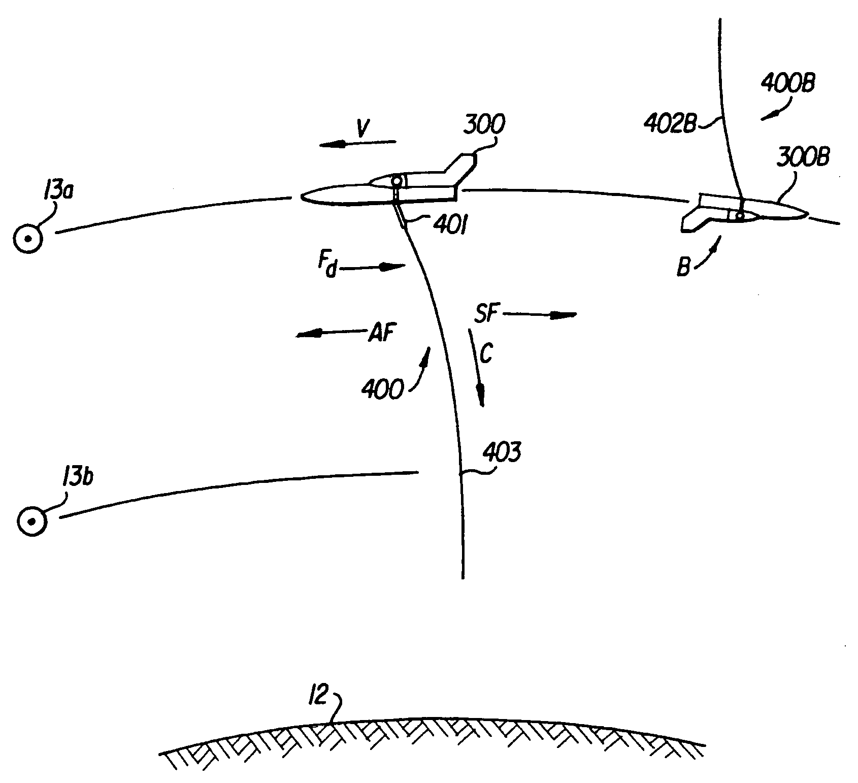
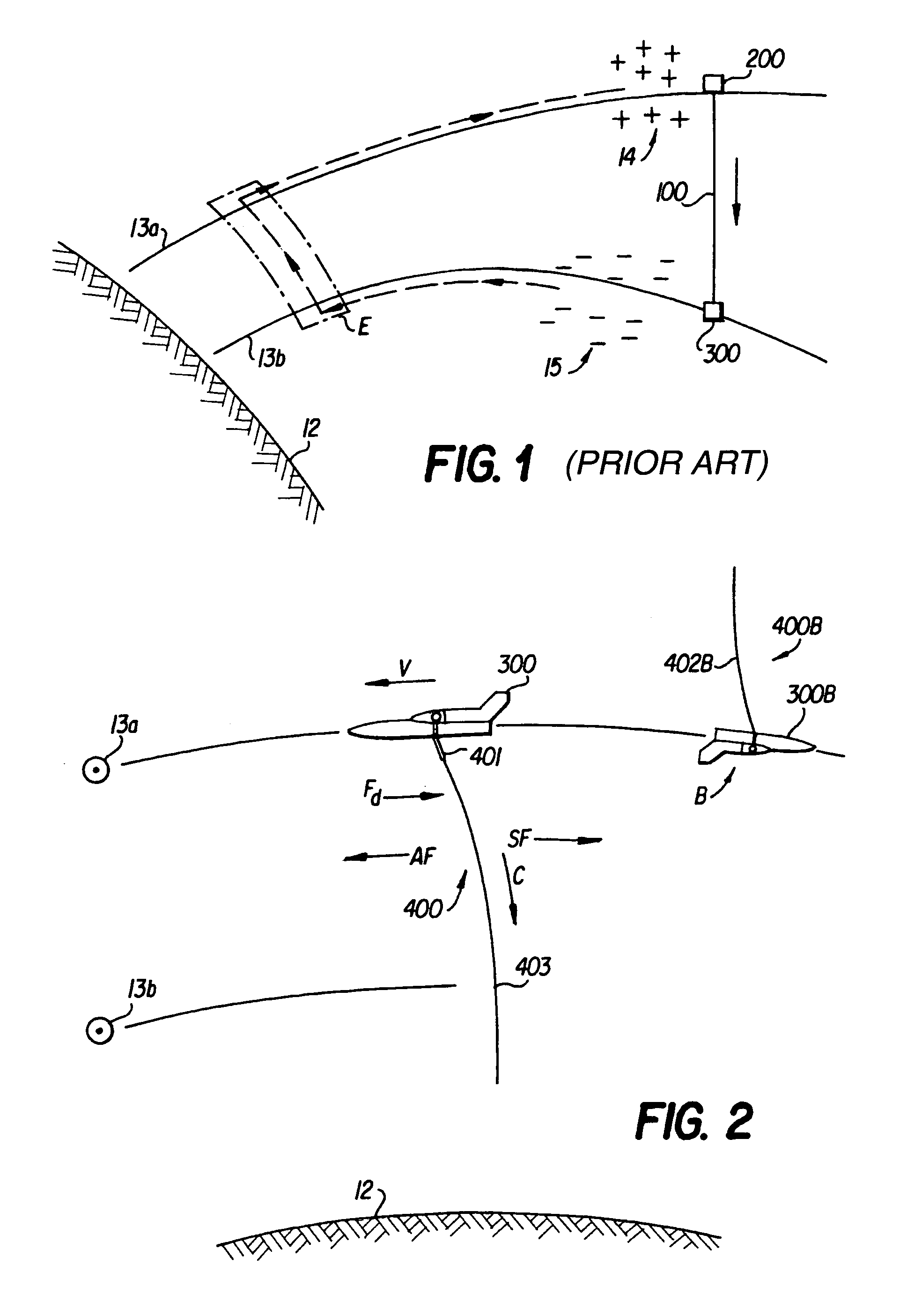
[0024]The electro-dynamic tether 400 according to the present invention is shown in FIG. 2. In the figure, a spacecraft 300 is orbiting the Earth 12 in the direction and speed V. A tether 400 is extended down towards the surface of the Earth from spacecraft 300 in order to provide thrust to the spacecraft, power various subsystems or charge batteries. The tether is separated into three sections, an insulating section 401 attached to spacecraft 300, a conducting section 402 attached to the insulating section extending therefrom and a non-conducting 403 section attached to the conducting section and extending therefrom.

[0025]Circle dots 13a and 13b represent the magnetic field lines of the Earth moving out of the page (to the left of the direction of travel V). The horizontal lines extending from the field lines 13a and 13b represent the change in field strength. As is shown in FIG. 2, spacecraft 300 is at a different field strength than the extended portion of conducting section 402....


PUM


Abstract

A tether system for providing thrust to or power subsystems of an artificial satellite in a low earth orbit. The tether has three main sections, an insulated section connected to the satellite, a conducting section connected to the insulating section for drawing in and releasing electrons from the space plasma and a non-conducting section for providing a tension to the other sections of the tether. An oxygen resistant coating is applied to the bare wire of the conducting section as well as the insulated wires of the insulated section that prevents breakdown during tether operations in the space plasma. The insulated and bare wire sections also surround a high tensile flexible polymer core to prevent any debris from breaking the tether during use.

Description

[0001]The invention described herein was made in performance of work under a NASA contract and by an employee of the United States Government and is subject to the provisions of Section 305 of the National Aeronautics and Space Act of 1958, as amended, Public Law 85-568 (72 Stat. 435; 42 U.S.C. §2457), and 35 U.S.C. §202, and may be manufactured and used by or for the Government of the United States of America for governmental purposes without the payment of any royalties thereon or therefor. In accordance with 35 U.S.C. §202, the Contractor elected not to retain title.FIELD OF THE INVENTION[0002]The principal utility of the present invention is in outer space, where it is useful for powering spacecraft subsystems, charging battery systems, raising the orbit of a satellite or lowering the orbit of a satellite. The satellite may be a manmade object, e.g., a spaceship or a telecommunications satellite or a space station, or a smaller celestial body orbiting a larger celestial body. Su...

Claims


Application Information

Patent Timeline
IPC IPC(8): B64G1/00
CPCB64G1/42B64G1/648
Inventor JOHNSON, CHARLES L.BALLANCE, JUDY L. C.WELZYN, KENNETH J.VAUGHN, JASON A.LORENZINI, ENRICOSCHULER, PETER S.
Owner NASA
Learn More