
Control of small distributed energy resources

Active Publication Date: 2006-10-03
WISCONSIN ALUMNI RES FOUND
View PDF19 Cites 105 Cited by
  • Summary
  • Abstract
  • Description
  • Claims
  • Application Information

AI Technical Summary

Benefits of technology

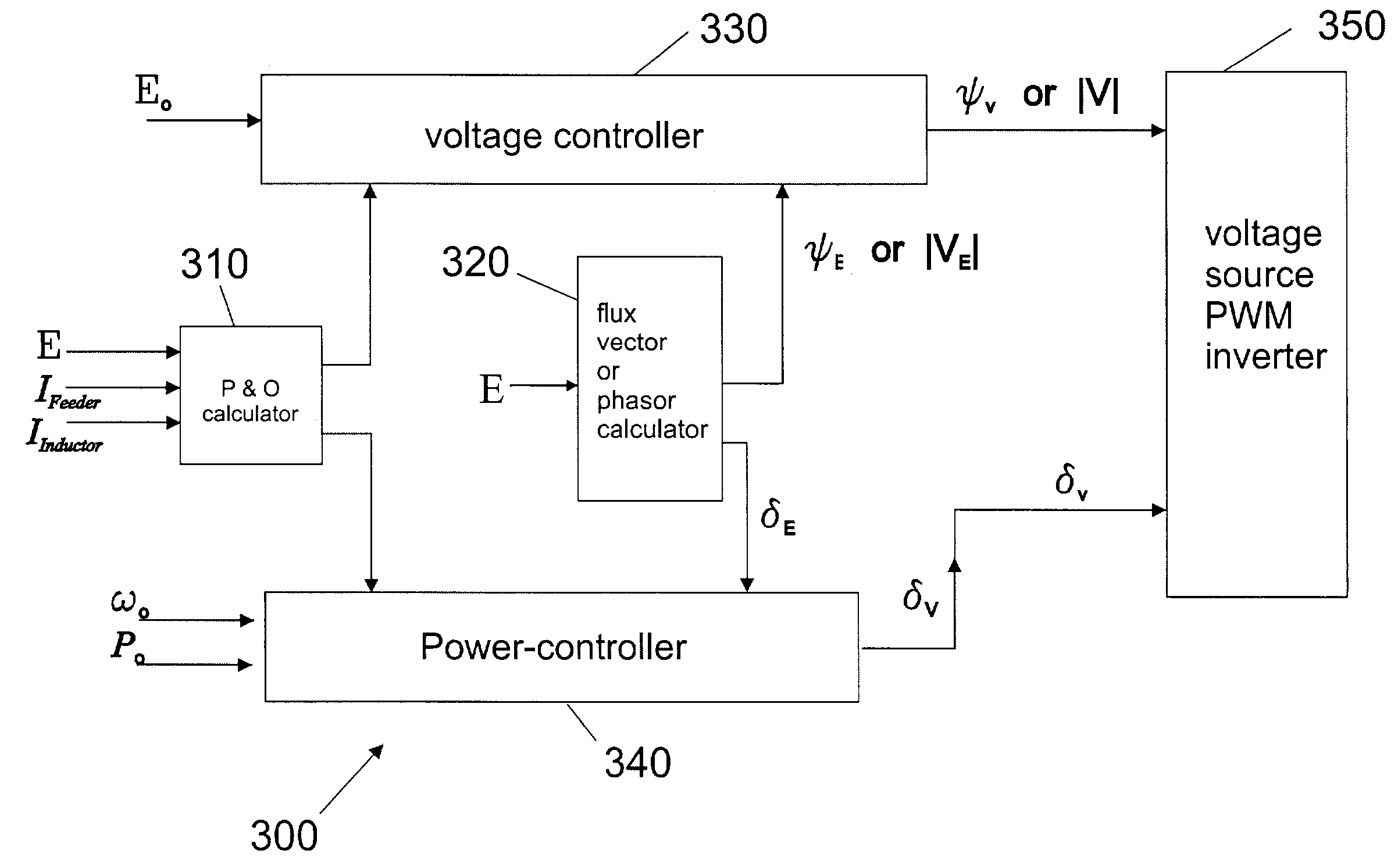
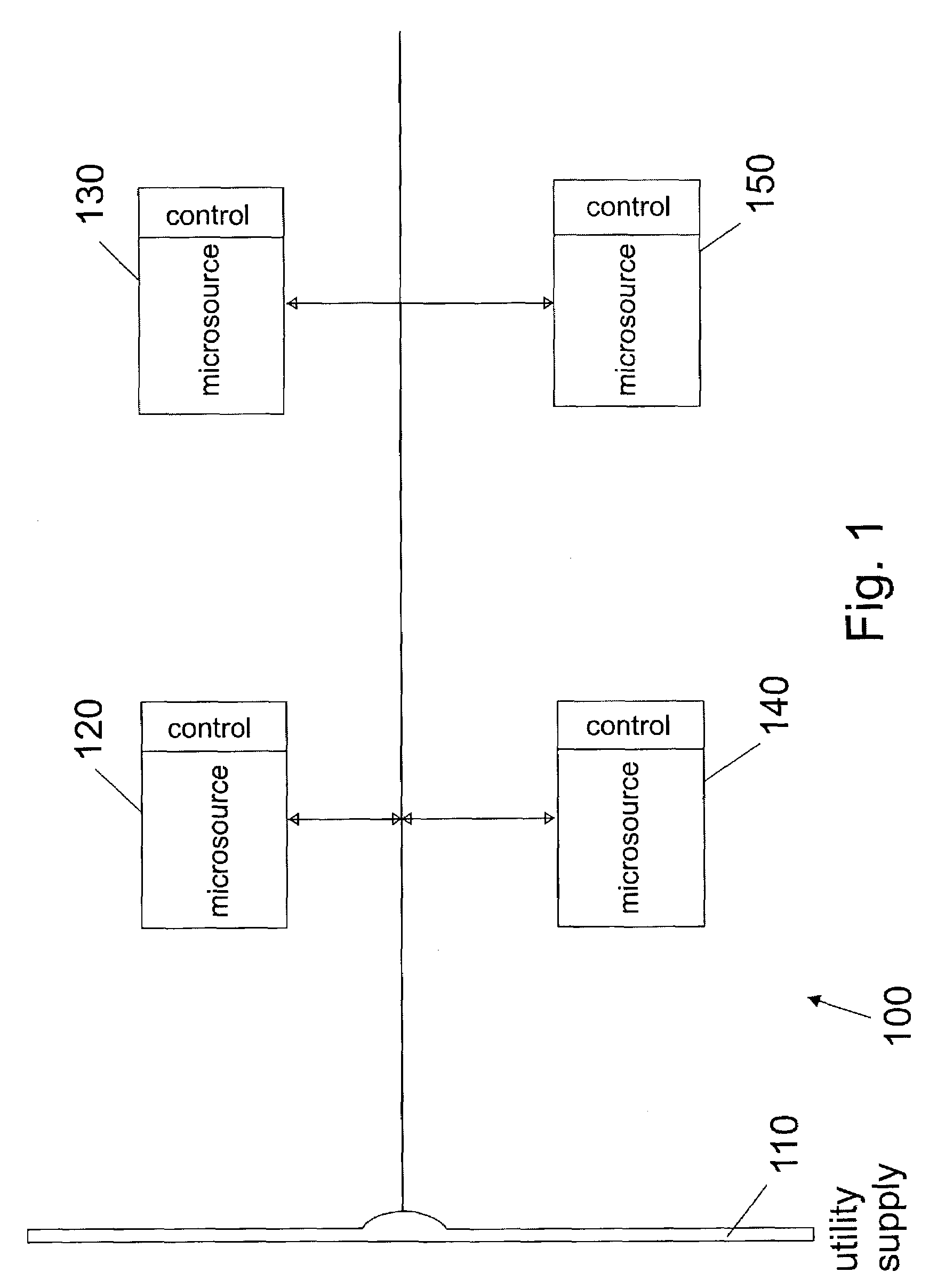
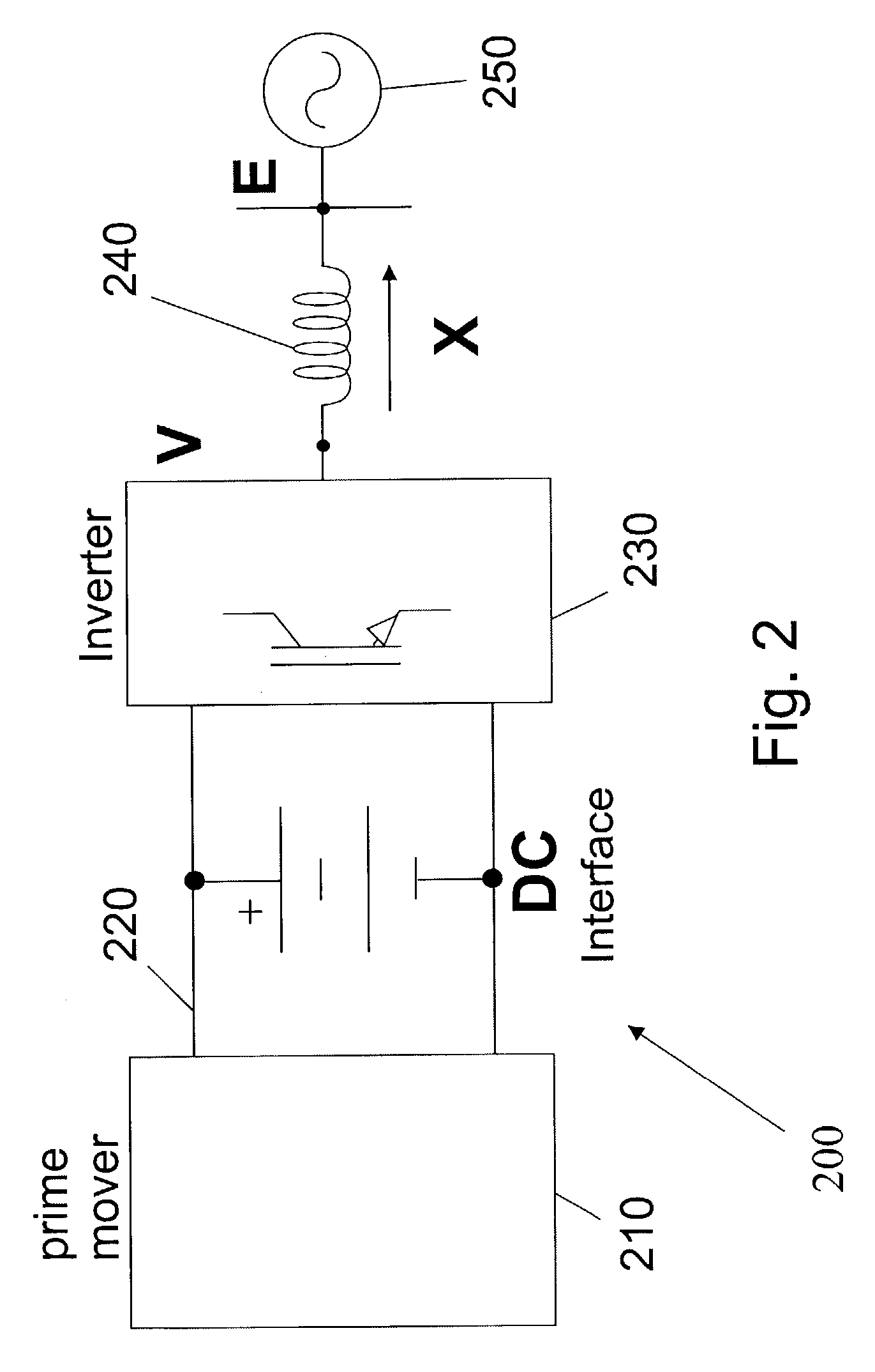
[0021]A microsource can be controlled in a microgrid system such that the microgrid can operate independently from a power grid or in cooperation with the power grid. The method of operation can include receiving inputs from voltage at a connection point, current injected by the microsource, and current in a feeder from a utility supply. The method reduces a local voltage set point as current injected by the microsource becomes more capacitive and increases the local voltage set point as current generated by the microsource becomes more capacitive.

Problems solved by technology

Construction of new large power generating plants has not kept pace with growing electricity demand.
Even if a sufficient number of new generating plants were built, the country's aging transmission and distribution systems are unlikely to reliably deliver the increased power supply that is needed.
Moreover, the cost of the upgrades required to enable today's power system to deliver the level of reliability being demanded is far in excess of what society has so far been willing to bear.
They offer high efficiency and low emissions but are currently expensive.
However, even fuels that contain no nitrogen emit NOx, which forms at high combustion temperatures from the nitrogen and oxygen in the air.
As a result, basic system problems include controlling the power feeder from the grid, the microsource's response speed, the sharing and tracking of loads among the distributed resources, the reactive power flow, the power factor, and the system's steady-state and transient stability cannot be achieved using methods developed over time for synchronous generators.
As such, power from a microsource in a DER system has not been independently controlled.

Method used


Image

  • Control of small distributed energy resources
  • Control of small distributed energy resources
  • Control of small distributed energy resources

Examples


Embodiment Construction

[0042]In the following description, for purposes of explanation, numerous specific details are set forth to provide a thorough understanding of exemplary embodiments of the invention. It will be evident, however, to one skilled in the art that the invention may be practiced without these specific details. In other instances, structures and devices are shown in block diagram form to facilitate description of the exemplary embodiments.

[0043]In some embodiments, hardwired circuitry may be used in place of, or in combination with, software instructions to implement the functions described. Thus, the embodiments described herein are not limited to any specific combination of hardware circuitry and software, nor to any particular source for the instructions executed by a computerized control system.

[0044]Exemplary embodiments of a system for and method of control of small distributed energy resources are described below. These exemplary embodiments can include distributed generators contr...


PUM


Abstract

A power electronics interface in a microsource controller allows efficient connection in a power system of small, low cost and reliable distributed generators such as microturbines, fuel cells and photovoltaic. Power electronics provide the control and flexibility to insure stable operation for large numbers of distributed generators. The power electronics controls are designed to insure that new generators can be added to the system without modification of existing equipment. A collection of sources and loads can connect to or isolate from the utility grid in a rapid and seamless fashion, each inverter can respond effectively to load changes without requiring data from other sources, and voltage sag and system imbalances can be corrected.

Description

STATEMENT REGARDING GOVERNMENT RIGHTS[0001]This invention was made with United States government support awarded by the following agencies:[0002]DOE DE-AC36-99-G010337[0003]NSF EEC-0119230The United States government has certain rights in this invention.FIELD OF THE INVENTION[0004]The present invention relates generally to power systems, including distributed energy resources (DER) systems and methods. More particularly, the present invention relates to control of small distributed energy resources.BACKGROUND OF THE INVENTION[0005]Construction of new large power generating plants has not kept pace with growing electricity demand. For example, in the western and northeastern regions of the United States, electricity demand has outpaced supply from power generating plants. At the same time, customer demand for even more highly reliable power is growing across the nation. Even if a sufficient number of new generating plants were built, the country's aging transmission and distribution ...

Claims


Application Information

Patent Timeline
IPC IPC(8): H02J1/12G05F1/70H02J3/38H02J3/46
CPCH02J3/46H02J3/381H02J2300/10H02J3/472
Inventor LASSETER, ROBERT H.PIAGI, PAOLO
Owner WISCONSIN ALUMNI RES FOUND
Learn More