
Mirror split brain avoidance

a technology of mirror split and brain, applied in the field of storage system transfer service, can solve the problems of data loss, data failure, and inability to recover data from the device,

Active Publication Date: 2006-09-19
NETWORK APPLIANCE INC
View PDF5 Cites 75 Cited by
  • Summary
  • Abstract
  • Description
  • Claims
  • Application Information

AI Technical Summary

Benefits of technology

[0022]Advantageously, the procedures described herein prevent the possibility that clients accessing the storage system will “see” out-of-date versions of the data either during transfer of service of the system during the disaster scenario or subsequently after the storage system is healed and service on the failed system has been restored. To that end, the inventive technique defends against silent access to out-of-date data subsequent to a disaster takeover, while providing continuity in the naming and identity of the surviving data set. Ordinal assignment of a volume is dynamic, persistent across reboot operations through the use of an ordinal claim and precedence settings provide a deterministic method for determining ordinal assignment. Mirroring operations continue uninterrupted if the surviving data set is up-to-date sufficient to resynchronize with potential source and target mirrors. In addition, healing of the storage subsystem instantiates both the surviving and failed data sets for comparison and resolution of conflicts. The inventive technique described herein handles partial failures of the storage system, i.e., handles partial or complete loss of the storage connection between the systems.

Problems solved by technology

In the operation of a disk array, it is anticipated that a disk can fail.
Data can be lost when one or more disks fail, making it impossible to recover data from the device.
A name conflict may also arise when a volume with a given name is disconnected from one system and connected to a different system that contains a volume with the same name.
Although prior systems provide a mechanism for resolution of name conflicts, such resolution is not consistent across reboot operations nor do they utilize a scheme for determining the ordering in which conflicts are resolved based on attributes of the conflicted volumes.
Examples of this latter state include failures due to missing disks and corrupted configuration data.
However, a scenario in which both a storage system and its data set fails may occur under a variety of circumstances, including but not limited to, power failures at the system / data set site (a temporary failure) and catastrophic loss of the physical location (a permanent failure).
A scenario of this latter form (termed a disaster scenario) is infrequent and highly disruptive to the client application environment.
A problem that may arise with such a mirrored volume configuration involves a “split-brain” situation wherein two divergent “views” of the data sets are created.
In this context, DS2 is lost as a result of being physically removed from the system for a period of time either by disconnecting the disks of the volume or shutting down power to the disks.
Typically, the problem arises after DS1 has moved forward.

Method used


Image

  • Mirror split brain avoidance
  • Mirror split brain avoidance
  • Mirror split brain avoidance

Examples


Embodiment Construction

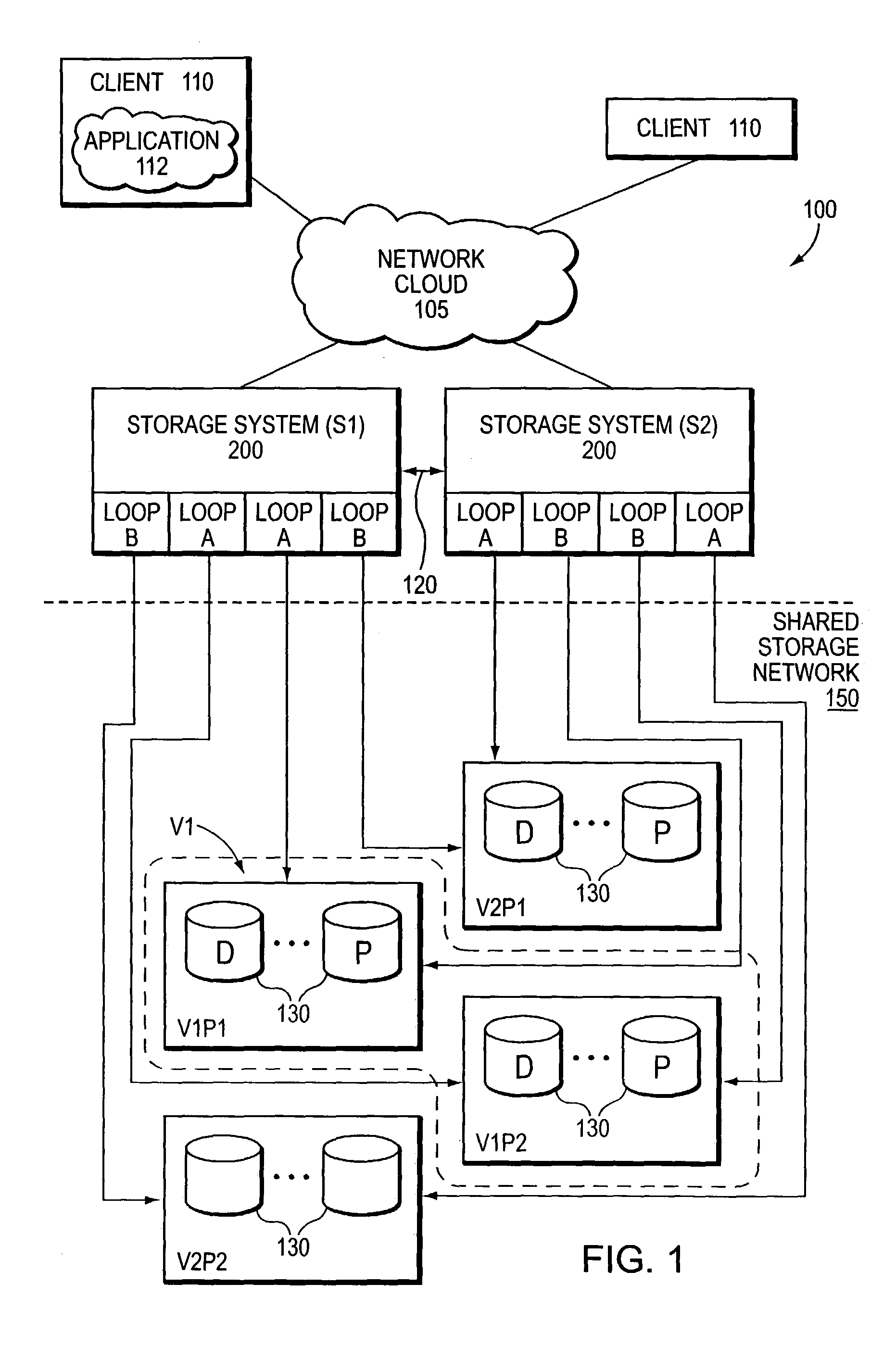
[0034]FIG. 1 is a schematic block diagram of a cluster failover (CFO) system configuration 100 comprising a pair of storage systems (S1, S2) 200 coupled by a dedicated, memory based cluster interconnect 120 that may use a variety of different technologies to provide a private communications mechanism. The clustered storage systems are also coupled to a shared point-to-point storage network 150, such as a storage area network (SAN) configured to store information. The information may be stored on any type of attached array of writable storage device media such as video tape, optical, DVD, magnetic tape, bubble memory, electronic random access memory, micro-electro mechanical and any other similar media adapted to store information, including data and parity information. However, as illustratively described herein, the information is preferably stored on the disks 130, such as HDD and / or DASD.

[0035]A plurality of clients 110 connects to each storage system 200 over a network cloud 105...


PUM


Abstract

A technique includes a set of procedures utilized during the transfer of service of a failed storage system to a surviving storage system of a cluster failover (CFO) configuration during a system outage, such as a disaster scenario. The procedures are executed by a RAID subsystem of the surviving storage system during disaster takeover, storage healing and node restart operations. The procedures prevent the possibility that clients accessing the storage system will see out-of-date versions of the data either during transfer of service of the system during the disaster scenario or subsequently after the storage system is healed and service on the failed system has been restored.

Description

FIELD OF THE INVENTION[0001]The present invention relates to storage systems and, more specifically, to a technique for transferring service of a storage system during system outages, such as a disaster scenario.BACKGROUND OF THE INVENTION[0002]A storage system typically comprises one or more storage devices into which data may be entered, and from which data may be obtained, as desired. The storage system includes a storage operating system that functionally organizes the system by, inter alia, invoking storage operations in support of a storage service implemented by the system. The storage system may be implemented in accordance with a variety of storage architectures including, but not limited to, a network-attached storage environment, a storage area network and a disk assembly directly attached to a client or host computer. The storage devices are typically disk drives organized as a disk array, wherein the term “disk” commonly describes a self-contained rotating magnetic medi...

Claims


Application Information

Patent Timeline
IPC IPC(8): G06F11/08G06F12/16
CPCG06F11/2069Y10S707/99953
Inventor SCHOENTHAL, SCOTTRODRIGUES, STEVEN H.ROWE, ALAN L.SEN SARMA, JOYDEEPCOATNEY, SUSAN M.
Owner NETWORK APPLIANCE INC
Learn More