
Data synchronization of multiple remote storage

a data synchronization and remote storage technology, applied in the field of data processing storage systems, can solve problems such as data regarding future ticketed reservations being lost, interludes of different data images being a problem, and businesses such as airline companies risk chaos, so as to reduce the effect of data synchronization

Inactive Publication Date: 2006-09-19
GOOGLE LLC
View PDF11 Cites 10 Cited by
  • Summary
  • Abstract
  • Description
  • Claims
  • Application Information

AI Technical Summary

Benefits of technology

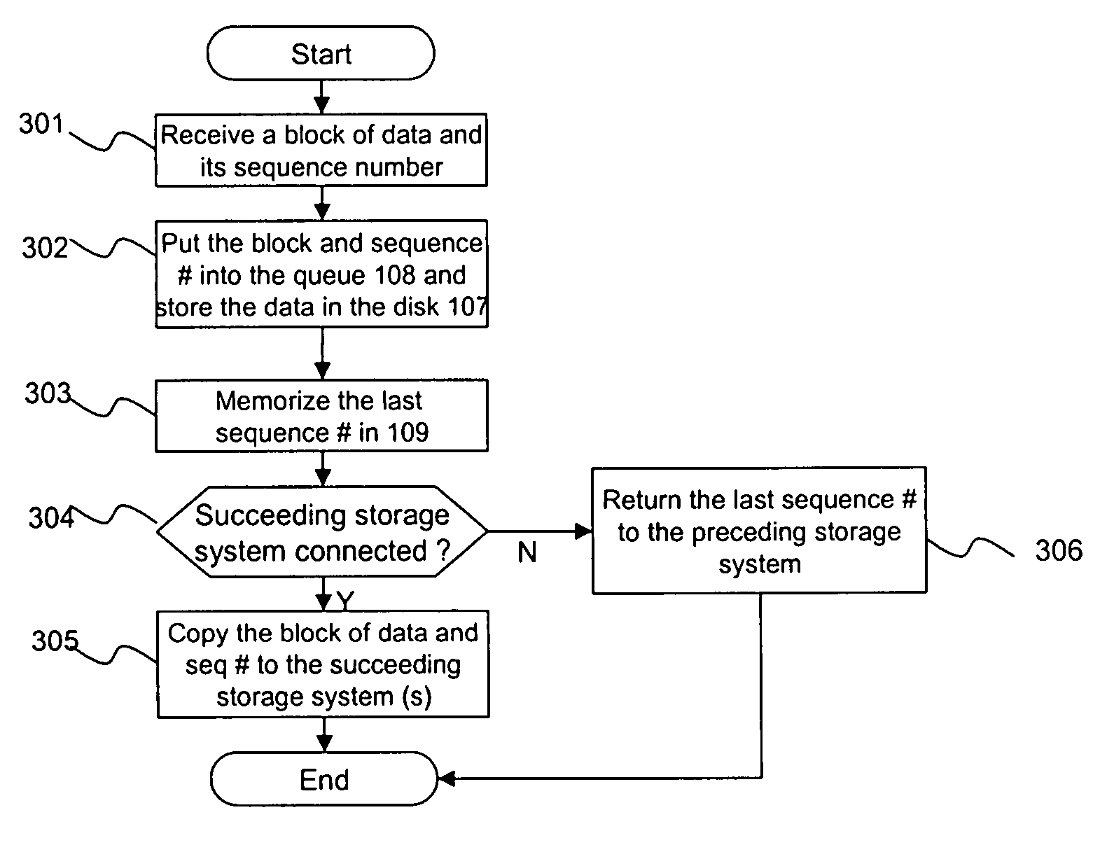
The present invention provides an improved data processing storage system by allowing data to be copied between storage subsystems and sharing the copy status with other storage subsystems. The last sequence number of each block of data is recorded in a queue in each storage subsystem and a table is used to keep track of the last sequence number of each preceding storage subsystem. This allows for efficient data synchronization in case of failure. Additionally, the invention includes a processor to search for the smallest last sequence number and compare it with the smallest last sequence number of other surviving storage subsystems to copy data from one system to another. The technical effects of the invention include improved data processing speed, reduced data storage capacity requirements, and improved data synchronization in case of failure.

Problems solved by technology

Businesses such as airline companies risk chaos should data regarding future ticketed reservations be lost.
These interludes of different data images can be a problem if the local facility fails.
Failure of the local storage facility can leave some remote storage facilities with data images that more closely, if not exactly, mirror that of the local storage facility before failure, while others have older “stale” data images that were never completely updated by the last update operation.
Thus, failure of the local storage facility may require the remote storage facilities to resynchronize the data among them to assure all have the same latest data image before restarting the system.
One problem which also must be addressed is recovery of the system in the circumstance where a “suspension” occurs during a remote copy operation.
One approach for resynchronizing remote copy operations is described in U.S. Pat. No. 6,092,066 entitled “Method and Apparatus for Independent Operation of a Remote Data Facility.” The technique described in this patent, however, only allows resynchronization in limited circumstances.
With certain types of more complex system suspensions, such as a combination of two failures, e.g., a link failure, cache overflow, and / or a drive failure, there is no ready solution to re-synchronizing the system which avoids reinitializing the system.
In these types of situations, because this technology does not assure that the configuration will have at least two copies available, a full copy of the volume is usually required for resynchronization.
When the primary site fails due to problems such as a disaster and the primary storage data becomes unavailable, computer systems start their jobs using data in the secondary storage systems.
If the storage systems are not synchronized, the data in the storage systems become inconsistent.
When several storage systems are used, each storage system has no way of knowing the copy progress or status of the other storage systems (i.e., what data has been copied).
It is virtually impossible to ascertain the differences among storage systems manually.
As a result, it may be necessary to copy all data in one storage system which is used for production to all other storage systems in order to synchronize the storage systems, which leads to unnecessarily huge data transaction and long completion time.

Method used


Image

  • Data synchronization of multiple remote storage
  • Data synchronization of multiple remote storage
  • Data synchronization of multiple remote storage

Examples


Embodiment Construction

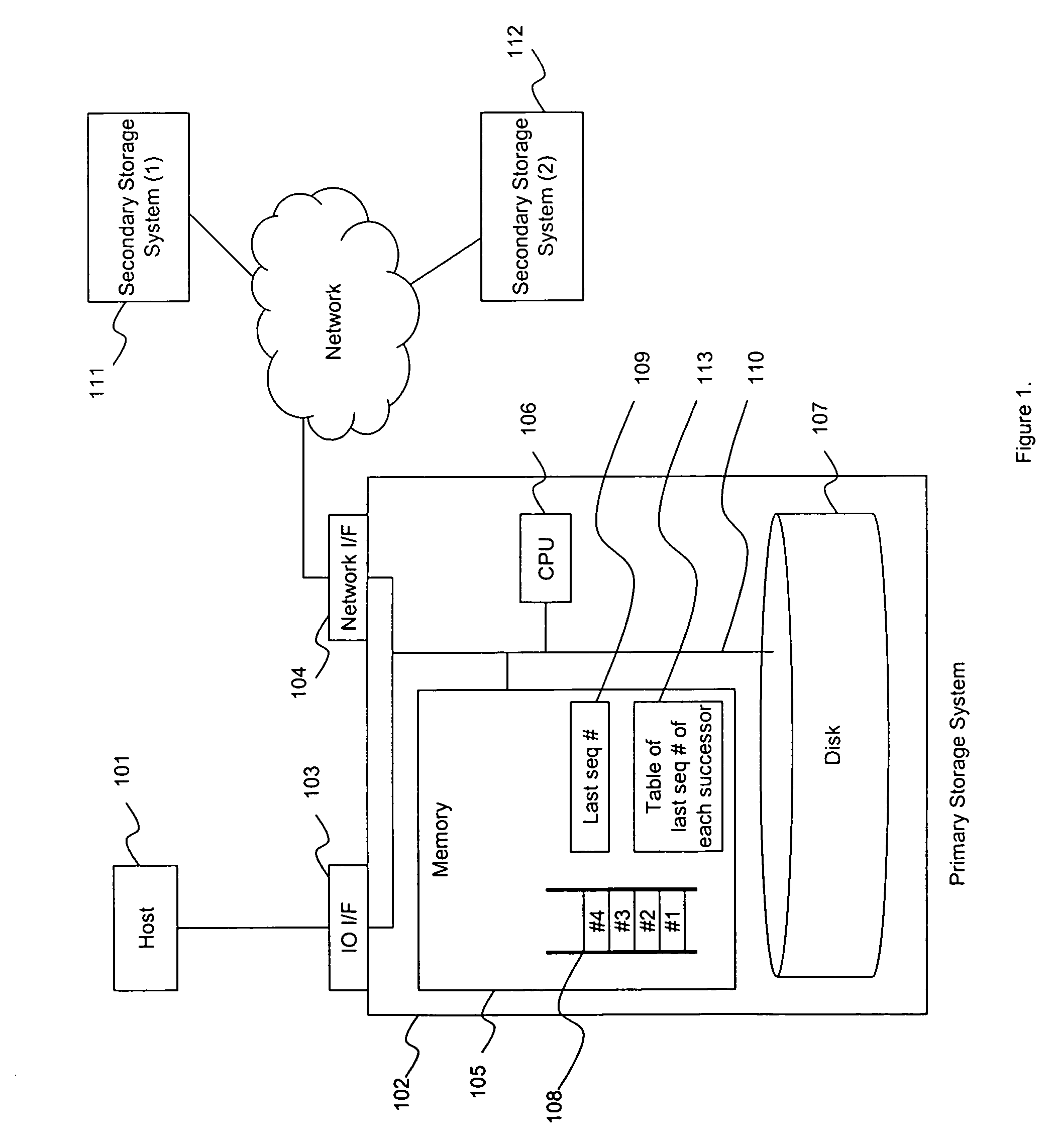
[0022]FIG. 1 shows a storage system 100 having a host system 101 and a plurality of storage subsystems. The storage subsystems include a primary storage system 102 and a plurality of secondary storage systems 111, 112. The host system 101 is connected to the primary storage system 102 through an IO interface 103 through which input and output are transmitted. Data or information entering the primary storage system 102 is processed by the processor or CPU 106 using the memory 105, and may be stored in the disk or storage medium 107, which may be RAID or just a bunch of disks (JBOD). The memory 105 includes a queue 108 for storing blocks of data and associated sequence numbers, a record 109 for storing the last sequence number, and a table 113 for storing last sequence numbers of succeeding storage systems, as described in greater detail below. An internal bus 110 is provided for conveying internal data. A network interface 104 is coupled to a network to facilitate communication with ...


PUM


Abstract

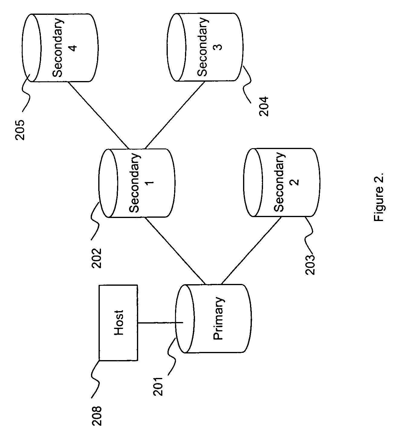
A storage system comprises a plurality of storage subsystems. One storage subsystem as a succeeding subsystem is configured to receive and store one or more blocks of data from another storage subsystem as a preceding subsystem. Each block of data has an associated sequence number in ascending order. The memory in each storage subsystem includes a queue to store the blocks of data and a sequence number associated with each block of data, a record to store a last sequence number associated with a last block of data received by the queue, and a table to store last sequence numbers stored in the last sequence number record gathered from each succeeding storage system. In some embodiments, a smallest last sequence number is determined from the last sequence numbers associated with the blocks of data in the storage subsystems. Blocks of data in the queue of each storage subsystem having associated sequence numbers less than or equal to the determined smallest last sequence number are deleted. In case of a failure of one or more storage subsystems, blocks of data are copied from the surviving storage subsystem having associated sequence numbers higher than the last sequence number of other surviving storage subsystems.

Description

CROSS-REFERENCES TO RELATED APPLICATIONS[0001]Not ApplicableBACKGROUND OF THE INVENTION[0002]The present invention relates generally to data processing storage systems which include a primary (or local) storage facility and two or more secondary (or remote) storage facilities that mirror at least certain of the data retained by the primary storage facility. More particularly, the invention relates to a method, and apparatus implementing that method, to synchronize the data at surviving storage facilities in the event of an interruption in copying data from one storage location to another storage location.[0003]Extensive use of data processing by commercial, governmental and other entities has resulted in tremendous amounts of data being stored—much of it of extreme importance to the day-to-day operation of such entities. For example, enormous numbers of financial transactions are now performed entirely electronically. Businesses such as airline companies risk chaos should data regar...

Claims


Application Information

Patent Timeline
Patent Type & Authority Patents(United States)
IPC IPC(8): G06F12/00G06F3/06G06F12/16
CPCG06F3/0617G06F3/0659G06F3/0689G06F11/2058G06F11/2082Y10S707/99955G06F11/2074Y10S707/99953G06F11/2071
Inventor OSAKI, NOBUYUKI
Owner GOOGLE LLC
Learn More