
System and method for recognizing markers on printed circuit boards

a technology of printed circuit boards and markers, applied in the field of system and method for detecting markers on printed circuit boards, can solve the problems of limiting the type of marker recognition process used and inefficient marker recognition process, and achieve the effect of simplifying the teaching process and minimizing the use of manual parameters

Inactive Publication Date: 2006-09-19
SIEMENS AG
View PDF11 Cites 23 Cited by
  • Summary
  • Abstract
  • Description
  • Claims
  • Application Information

AI Technical Summary

Benefits of technology

[0015]The present invention is adapted to recognize all types of markers because it uses multiple features and it can be trained for specific markers by presenting sample images of both classes (good/bad). Further, because adaptive techniques are applied, the teach-

Problems solved by technology

The availability and use of such varying marker types can render a marker recognition process inefficient if the type of marker used is not particularly compatible with the recognition software.
Furthermore, there are several types of manufacturing processes that are implemented in electronic manufacture, which can limit the type of marker recognition process used.

Method used


Image

  • System and method for recognizing markers on printed circuit boards
  • System and method for recognizing markers on printed circuit boards
  • System and method for recognizing markers on printed circuit boards

Examples


Embodiment Construction

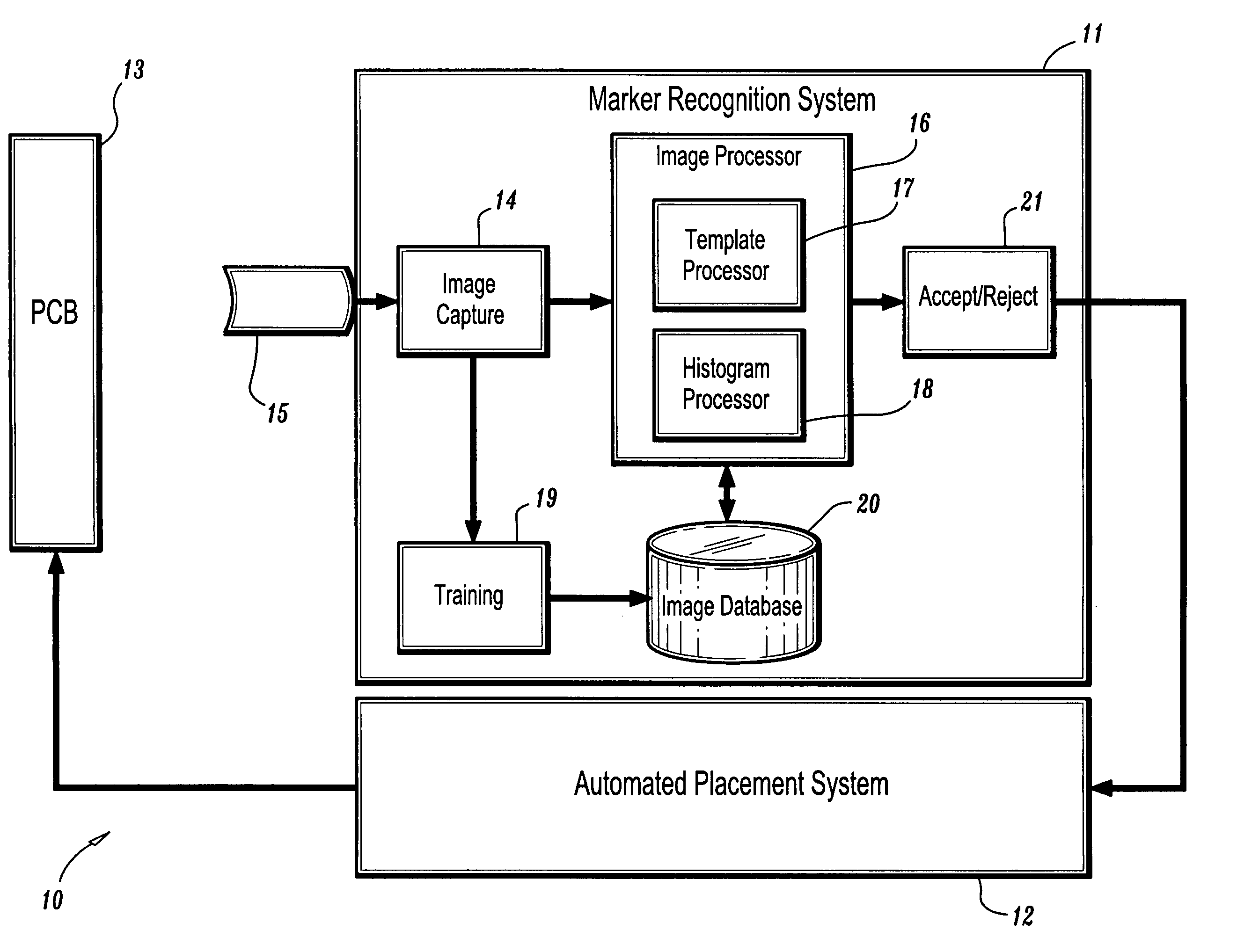
[0027]It is to be understood that the system modules and method steps described herein in accordance with the present invention may be implemented in various forms of hardware, software, firmware, special purpose processors, or a combination thereof. Preferably, the present invention is implemented in software as an application comprising program instructions that are tangibly embodied on one or more program storage devices (e.g., magnetic floppy disk, RAM, CD ROM, and ROM), and executable by any device or machine comprising suitable architecture. It is to be further understood that since the system modules and method steps depicted in the accompanying FIGURES are preferably implemented in software, the actual connections between the system modules and the logical flow of the process steps may differ depending upon the manner in which the present invention is programmed. Given the teachings herein, one of ordinary skill in the related art will be able to contemplate these and simila...


PUM


Abstract

A system and method for recognizing markers on, e.g., a PCB (printed circuit board). In one aspect, a system for recognizing a marker in an image comprises an image capture module (14) for extracting image features associated with an input image of a ROI (region of interest) captured through a lens 15, an image processor (16) comprising a first marker recognition processor (17) for recognizing a marker in the input image based on a normalized correlation and a second marker recognition processor (18) for recognizing a marker in the input image based on gray value histograms; a training module 19 for building template images and histograms that are used by the image processor (16) to detect a marker in the input image and a database (20) for indexing and storing trained template images and trained histograms.

Description

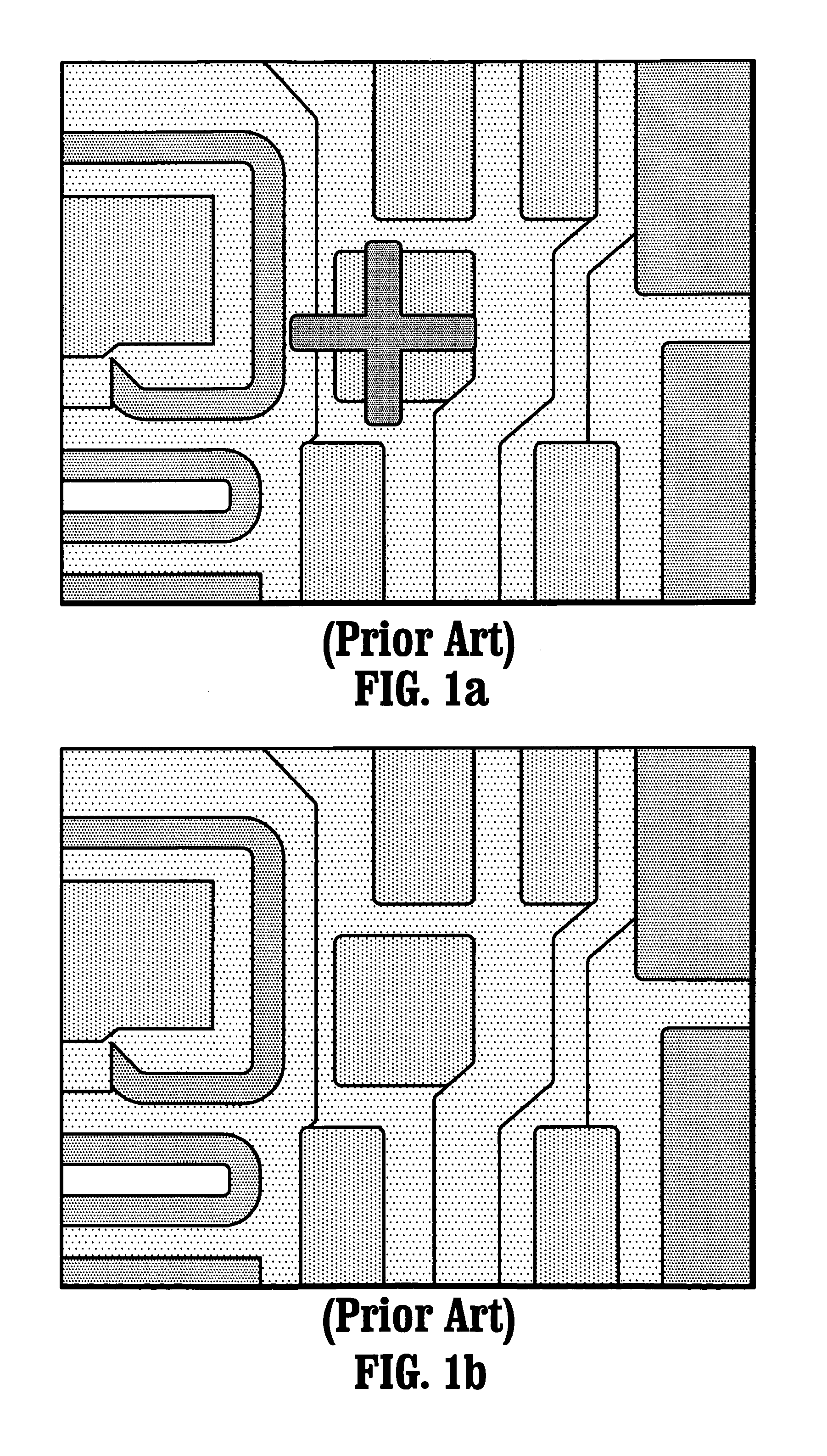
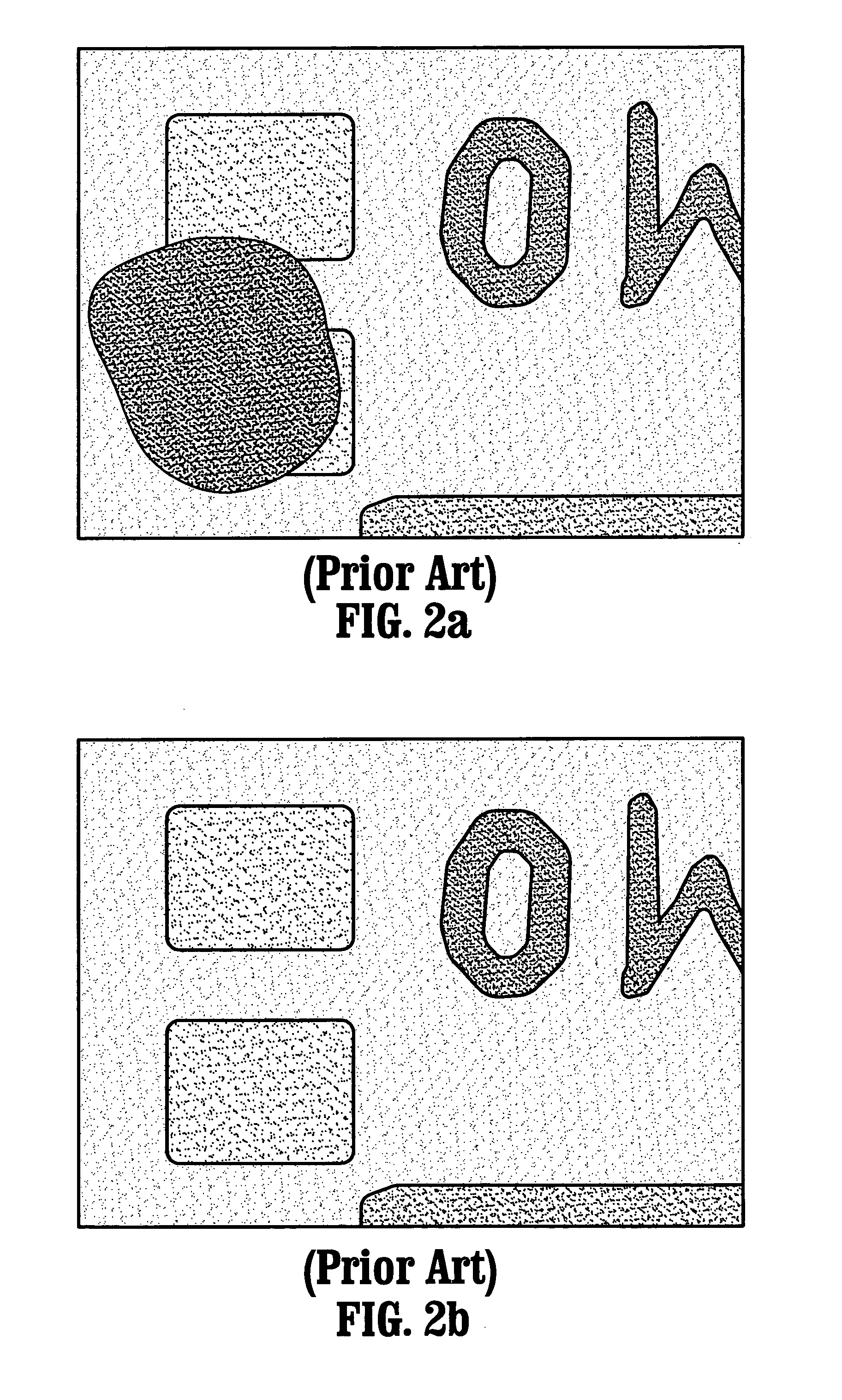
BACKGROUND[0001]1. Technical Field[0002]The present invention is generally related to a system and method for detecting markers on a PCB (printed circuit board) and, in particular, to a system and method for detecting markers on a PCB using an image processing technique based on histogram and template features.[0003]2. Description of Related Art[0004]Currently, electronic manufacturing is one of the major application fields of machine vision systems. In particular, before electrical components are placed on a PCB, the board and the components are inspected thoroughly in order to achieve high yield and to reduce repair costs. After inspection, defective circuits are marked so that they can be sorted from non-defective circuits and terminated from further processing.[0005]Various types of markers are implemented by manufacturers in their manufacturing processes. For instance, as shown in FIG. 1a, one type of marker that is used to mark a defective circuit is a laser graving (i.e., a c...

Claims


Application Information

Patent Timeline
IPC IPC(8): G06K9/00G06V10/40H05K13/08
CPCG06K9/3241G06K9/46H05K13/08G06K9/6212G06K9/4647H05K1/0269H05K2201/09936H05K13/0812G06V10/255G06V10/40G06V10/507G06V10/758
Inventor NEUBAUER, CLAUSFANG, MING
Owner SIEMENS AG
Learn More